The ALL Florida Online Corvette Club


Corvette Top Sites

Go Back   The ALL Florida Online Corvette Club > General Corvette Forums > Maintenance, Mods, & Tips

      Photo Gallery Screen Saver!      

Maintenance, Mods, & Tips Mods | Tips | Repairs & Troubleshooting

Reply
Thread Tools Display Modes
Unread 02-08-2012, 01:59 PM   #1361
navy2kcoupe
!ereH nI depparT m'I pleH
 
navy2kcoupe's Avatar
 
Join Date: Jan 2007
Location: 25 miles south of Boston, MA. Also have a house in Dunedin FL.
Posts: 1,927
Name : Andy Anderson
navy2kcoupe has disabled reputation
Default

Don't hack the firewall, move the engine forward.....
Good luck finding a solution Rich.
Andy
__________________
Andy Anderson - PROUD-VIETNAM-VETERAN.
VIETNAM VETERANS CORVETTE CLUB - FOUNDING MEMBER #1
https://sites.google.com/site/vietna...scorvetteclub/
navy2kcoupe is offline   Reply With Quote
Unread 02-08-2012, 02:34 PM   #1362
CorvetteJohn
Deceased
 
Join Date: Mar 2009
Location: Muncie, Indiana
Posts: 147
Name : John Robinson
CorvetteJohn is on a distinguished road
Default

I think I am confusing you with my idea so I hope this will make it a little clearer as to what I see as a fix for the fuel rail plug problem.
Name:  BAnjo.jpg
Views: 893
Size:  18.8 KB
CorvetteJohn is offline   Reply With Quote
Unread 02-08-2012, 03:59 PM   #1363
Rich Z
Internet Sanitation Engineer
 
Rich Z's Avatar
 
Join Date: Mar 2006
Location: Crawfordville, FL
Posts: 15,126
Name : Rich Zuchowski
Rich Z will become famous soon enoughRich Z will become famous soon enough
Default

Quote:
Originally Posted by CorvetteJohn View Post
I think I am confusing you with my idea so I hope this will make it a little clearer as to what I see as a fix for the fuel rail plug problem.
Attachment 5486
Yes, that would work fine, I think. The problem is FINDING it.

Does anyone happen to know offhand what the threading is on the end of those FAST fuel rails?
__________________
Rich Z is offline   Reply With Quote
Unread 02-08-2012, 04:17 PM   #1364
CorvetteJohn
Deceased
 
Join Date: Mar 2009
Location: Muncie, Indiana
Posts: 147
Name : John Robinson
CorvetteJohn is on a distinguished road
Default

Take a look here for starters

https://www.google.com/search?source...w=1036&bih=711
CorvetteJohn is offline   Reply With Quote
Unread 02-08-2012, 06:23 PM   #1365
Rich Z
Internet Sanitation Engineer
 
Rich Z's Avatar
 
Join Date: Mar 2006
Location: Crawfordville, FL
Posts: 15,126
Name : Rich Zuchowski
Rich Z will become famous soon enoughRich Z will become famous soon enough
Default

Quote:
Originally Posted by CorvetteJohn View Post
Yeah, that looks promising. I just have to figure out what thread is in the fuel rails. The only thing I can come up with is something like "-8 AN ORING" but I have no idea what that really is....

Thanks....
__________________
Rich Z is offline   Reply With Quote
Unread 02-09-2012, 06:40 AM   #1366
CorvetteJohn
Deceased
 
Join Date: Mar 2009
Location: Muncie, Indiana
Posts: 147
Name : John Robinson
CorvetteJohn is on a distinguished road
Default

Another thought has just occured to me. When you find out what the thread size is on the rail you might think about the 90 degree banjo. That way you would be able to run the return line back along the fuel rail for a neater installation.

I believe if it says 8an washer then the thread is probably the same as an 8an hose fitting.

Went to the Fast rails site and now I see what they are doing. The part I thought was a reducer is actually an adaptor so you can connect the female fitting from the hose to the fuel rail.

If you have an 8an male end laying around you could see if it will go into the fuel rail in place of all those adapters. If so you will know the size of the fuel rail thread. Then all you need is the banjo bolt for that size and the banjo for the bolt. I hope this helps solve this problem.

Last edited by CorvetteJohn; 02-09-2012 at 07:23 AM.
CorvetteJohn is offline   Reply With Quote
Unread 02-09-2012, 11:40 AM   #1367
Rich Z
Internet Sanitation Engineer
 
Rich Z's Avatar
 
Join Date: Mar 2006
Location: Crawfordville, FL
Posts: 15,126
Name : Rich Zuchowski
Rich Z will become famous soon enoughRich Z will become famous soon enough
Default

I've seen two designations of the threads in the fuel rail (1) -8 SAE and (2) -8 AN O-RING.

But yeah, I think getting a male fitting that would screw directly INTO the end of the rail would be better than a female fitting that fits onto the F.A.S.T. fitting and perhaps give me the clearance I need.

And I think it's a 180 fitting you are referring to as that would be a "C" shape and probably need less clearance than a 90 degree, which would be perpendicular to the rail. I'm going to see if they make a 120 and 150 degree fitting as well. If I do have to cut the firewall, I need to keep the damage to the bare minimum.
__________________
Rich Z is offline   Reply With Quote
Unread 02-09-2012, 03:41 PM   #1368
shakedown067
Sinister C4
 
shakedown067's Avatar
 
Join Date: Jan 2007
Location: Largo, FL
Posts: 1,223
Name : Eric G
shakedown067 is on a distinguished road
Default

Whoa, hadn't checked-in in a while. Glad to see Kenny was able to drop by and help you out. Now, you just need him to stop by more often. LOL
shakedown067 is offline   Reply With Quote
Unread 02-09-2012, 07:33 PM   #1369
Rich Z
Internet Sanitation Engineer
 
Rich Z's Avatar
 
Join Date: Mar 2006
Location: Crawfordville, FL
Posts: 15,126
Name : Rich Zuchowski
Rich Z will become famous soon enoughRich Z will become famous soon enough
Default

In reference to the earlier posts about the vacuum line to the fuel pressure regulator, the guy who is going to be doing my tuning recommends that I DO have the vacuum line hooked up.

I've been doing some reading about this, and apparently there are two ways to control the issue of variable fuel amounts needed from idle to WOT. The problem is that there is MORE vacuum available at the fuel injectors at idle than at WOT, even to the point where at IDLE, the injectors themselves are actually subject to a suction effect that will draw out more fuel than injectors simply being opened at zero vacuum. I'm still trying to wrap my brain around some of this so bear with me.

Anyway, there are two methods used to adjust the actual amount of fuel that the PCM calculates for the injectors to provide that will be variable depending on the vacuum inside the manifold and referenced via the MAP sensor. One method is via the vacuum line going to the fuel pressure regulator which will then mechanically control the amount of fuel pressure it provides to the fuel rails. In this case, the regulator provides less fuel pressure at high vacuum levels and increasingly more pressure as vacuum is reduced and even going into positive pressure (boost for forced induction). The other method, and the one that is used in the stock C5 Corvettes (probably other generations, too), is to do this programmatically via something called the Injector Flow Rate Table. Which looks something like this...
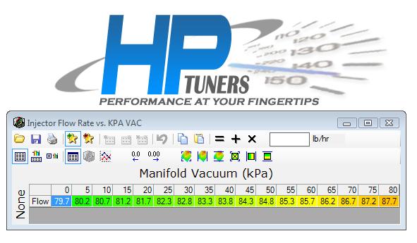


What this table does is programmatically act like what the vacuum line does that would go to the fuel pressure regulator. That is, it adjusts the amount of fuel referenced to the vacuum in the intake manifold that the PCM commands the fuel injectors to deliver to the cylinders. As you can see in the table above, the values are variable depending upon vacuum in the intake manifold. If the vacuum line were hooked up to the fuel pressure regulator, than those values would all be the same, which would be the actual flow rate of the injectors.

Now there is a lot of negative logic going on, that I am still trying to come to grips with, but basically kPa is actually PRESSURE, so 0 kPa means zero pressure, which means MAX vacuum (idle), and the value at 80 kPa means max pressure (up to sea level barometric pressure), which means zero vacuum (WOT - or pretty much ambient barometric pressure). Basically the amount of air coming into the engine has stabilized to where all the air needed is being provided.

Also note that the higher the values in the cells in the table, the LOWER amount of fuel being commanded to the fuel injectors. In effect, the table TELLS the PCM the flow rate of the injectors for a given amount of vacuum. The fuel injectors I have in that engine are rated at 72 lb, so it appears that this table is fooling the PCM in my car into thinking that the injectors are LARGER than they actually are, so that it will command a smaller duration opening of the injectors as the PCM tries to calculate how much fuel that the injector needs to deliver to the cylinder, and therefore run leaner than if the 72 lb values were being used. Since the PCM thinks the injectors are larger, it needs to hold the duration of the injector being opened a LESSER amount of time. So, in effect, the smaller the number in that table the longer the duration, and therefore MORE fuel, being commanded to the fuel injectors. Like I said, NEGATIVE logic here...

Now, looking at that IFR table above, it's really confusing, at least to me. 100 kpa is actually 14.5 psi, which is pretty close to sea level air pressure (14.7 psi). So the assumption must be that the furtherest right hand cell must be WOT, and the left most cell must be idle, IF we are really talking about kPa values for that table. But if this is true, the VALUES in those cells are the REVERSE of what they should be. At idle, the value in that cell is 79.7, and at WOT, that cell is 87.7. So what this means is that the PCM is being hoodwinked into believing that thru all levels of manifold vacuum, the injectors are LARGER than the 72 lbs injectors I actually have. And more to the point of my confusion, the injector values at idle will deliver MORE fuel than the injector values indicated at WOT. Remember, smaller values will deliver MORE fuel than the larger values in that table.

The only way this table does make sense to me is if those cell labels are NOT actually kPa, but instead a relative VACUUM level, meaning that the table actually is indicating WOT at the left most cell, and IDLE at the rightmost cell. Then the values in those cells DO make sense, with less fuel being provided at idle and MORE fuel being provided at WOT.

I know the above is probably a jumbled mess, but I'm just trying to figure this all out, and maybe trying to EXPLAIN it will help me UNDERSTAND it a little better.... So if anyone else can figure this out and explain it to me, PLEASE do.
__________________
Rich Z is offline   Reply With Quote
Unread 02-10-2012, 12:05 AM   #1370
Rich Z
Internet Sanitation Engineer
 
Rich Z's Avatar
 
Join Date: Mar 2006
Location: Crawfordville, FL
Posts: 15,126
Name : Rich Zuchowski
Rich Z will become famous soon enoughRich Z will become famous soon enough
Default

Got the driver's side half shaft out today. That one was MUCH easier to get out. Probably because I've been spraying it with PB Blaster for a while now. And that GM tool for the job probably helped some.

Also got the hub separated from the knuckle and will be cleaning up all the stuff before I put the new shaft back in and put everything back together again. The second time doing this almost feels like old hat to me. Probably because I kinda feel like I know what I'm doing this time. On the other side, most of the time I was thinking, "Oh Lordy, what am I getting myself into now?"
__________________
Rich Z is offline   Reply With Quote
Reply

Tags
427, aaron scott, chris harwood, rhs block, south georgia corvette, xtrememotorsports


Currently Active Users Viewing This Thread: 3191 (0 members and 3191 guests)
 

Posting Rules
You may not post new threads
You may not post replies
You may not post attachments
You may not edit your posts

BB code is On
Smilies are On
[IMG] code is On
HTML code is Off
Forum Jump

Similar Threads
Thread Thread Starter Forum Replies Last Post
bits of nitrous info grumpyvette Tech and How-To Articles 5 11-24-2008 04:02 PM
Decoding a Corvette's V8 Casting Numbers and Engine Stamps RSS Feed Corvette News Feeds 0 12-11-2007 10:26 AM
Removing The Engine From A C5 Corvette - Removal Procedures Part: 1 RSS Feed Tech and How-To Articles 0 10-04-2007 01:05 AM
Building A 427 For Today's World RSS Feed Tech and How-To Articles 0 10-04-2007 01:05 AM
New for 2008 - LS3 Motor with 430 HP! DocDye TAMPA BAY VETTES CLUB 0 04-29-2007 04:45 PM


All times are GMT -4. The time now is 02:24 AM.


Powered by vBulletin® Version
Copyright ©2000 - 2024, Jelsoft Enterprises Ltd.
Page generated in 0.10796905 seconds with 12 queries
All material copyrighted by CorvetteFlorida.com and
the respective owners of the material posted.