The ALL Florida Online Corvette Club


Corvette Top Sites

Go Back   The ALL Florida Online Corvette Club > General Corvette Forums > Maintenance, Mods, & Tips

      Photo Gallery Screen Saver!      

Maintenance, Mods, & Tips Mods | Tips | Repairs & Troubleshooting

Reply
Thread Tools Display Modes
Unread 07-30-2012, 06:31 PM   #1761
Rich Z
Internet Sanitation Engineer
 
Rich Z's Avatar
 
Join Date: Mar 2006
Location: Crawfordville, FL
Posts: 15,127
Name : Rich Zuchowski
Rich Z will become famous soon enoughRich Z will become famous soon enough
Default

And here's some various pics I took of the driveshaft itself.


Notice the aluminum scraped onto the bolts holding the front input shaft onto the carbon fiber shaft. Obviously there was some substantial movement FORWARD of that shaft in the torque tube.
__________________
Rich Z is offline   Reply With Quote
Unread 07-30-2012, 08:46 PM   #1762
Rich Z
Internet Sanitation Engineer
 
Rich Z's Avatar
 
Join Date: Mar 2006
Location: Crawfordville, FL
Posts: 15,127
Name : Rich Zuchowski
Rich Z will become famous soon enoughRich Z will become famous soon enough
Default

To further muddy the waters about what the heck happened, I brought home the pilot bearing that Shane pulled from my crank.

First off, here's a couple of pics that I captured from the video I took of Chris Harwood installing the pilot bearing while he was putting the clutch stuff together on my engine.


Now the following is what I found when just doing a Google search for a C5 pilot bearing..


I would say that the bearing Chris Harwood installed looks pretty similar to the later picture.

Now, here's some pics of the pilot bearing that Shane extracted from my crank..


**Just a note, that the damage you see on one side of the bearing happened when the bearing was extracted from the crankshaft.**


I'm sorry, but I just don't know what to make of this. Was my pilot bearing changed out while at Aaron Scott's shop? If so, why does it look so different from what Chris Harwood originally put in there?
__________________
Rich Z is offline   Reply With Quote
Unread 07-31-2012, 12:48 AM   #1763
Rich Z
Internet Sanitation Engineer
 
Rich Z's Avatar
 
Join Date: Mar 2006
Location: Crawfordville, FL
Posts: 15,127
Name : Rich Zuchowski
Rich Z will become famous soon enoughRich Z will become famous soon enough
Default

I guess what bugs me about this is that I feel that I need to find out if this driveshaft moving forward in the torque tube was the cause of everything else or, is it just another symptom of something else not found yet that caused that to happen. I don't feel like I have found the smoking gun yet.

Another piece of the puzzle is shown here, I think.


Look at those marks on the shaft going into the spindle. It appears that someone beat pretty hard on it, evidently trying to shove it forward. So did whoever it was beat it hard enough to BREAK something, and that allowed the driveshaft to move forward in the torque tube?

That's what I am trying to figure out.

Also, what do you think the chances are that the bearing shown in the above photo is a brand new one like Chris Harwood told me was put onto that shaft?
__________________
Rich Z is offline   Reply With Quote
Unread 07-31-2012, 03:15 AM   #1764
Rich Z
Internet Sanitation Engineer
 
Rich Z's Avatar
 
Join Date: Mar 2006
Location: Crawfordville, FL
Posts: 15,127
Name : Rich Zuchowski
Rich Z will become famous soon enoughRich Z will become famous soon enough
Default

In reference to the above pics concerning the pilot bearing, I'm trying to resolve a conflict in my mind with what the heck I am seeing in the crankshaft.

Here's a pic that I took of the crankshaft end as it exists now where Shane removed the pilot bearing.


And here's a couple of pics that I captured from before Chris Harwood put that original pilot bearing into the crankshaft.


Man, I dunno, but the ONLY thing that makes sense to me when I look at these photos as well as the pilot bearing that Shane removed is that the outer shell of that pilot bearing is STILL in the crank. And it is that bearing shell that the drive shaft apparently bored into, NOT the crank itself. Look at that silver colored plug in the back of that hole. There is no way to get that thing in and out of there in the top pic, as is. The plug is the same diameter of the larger hole as shown in the bottom two pics. So obviously there is something in that hole now making it appear to be smaller than that plug is. It's either that part of that pilot bearing is still in there, which will then resolve the problem as to why the pilot bearing Shane removed is smaller than the one I show in pics of Chris Harwood installing, or I'm just losing my friggin' mind with this stuff.

Again, here's a pic of what the C5 pilot bearing is SUPPOSED to look like.


Here's a pic of what Shane extracted.


Taking this all together, that brass looking outer shell of the actual bearing HAS to still be in there.
__________________
Rich Z is offline   Reply With Quote
Unread 07-31-2012, 05:48 AM   #1765
ironhorse
Road Warrior
 
ironhorse's Avatar
 
Join Date: Aug 2008
Location: S. Florida
Posts: 220
Name :
ironhorse is on a distinguished road
Default

Hey Rich. It looks like the outer shell of the pilot bearing is still lodged in the back of the crank...I suggest you get ahold of a new pilot bearing for your car, and look at it closely to see if it can be seperated from it's outer shell?...
ironhorse is offline   Reply With Quote
Unread 07-31-2012, 10:57 AM   #1766
Rich Z
Internet Sanitation Engineer
 
Rich Z's Avatar
 
Join Date: Mar 2006
Location: Crawfordville, FL
Posts: 15,127
Name : Rich Zuchowski
Rich Z will become famous soon enoughRich Z will become famous soon enough
Default

Quote:
Originally Posted by ironhorse View Post
Hey Rich. It looks like the outer shell of the pilot bearing is still lodged in the back of the crank...I suggest you get ahold of a new pilot bearing for your car, and look at it closely to see if it can be seperated from it's outer shell?...
My guess is that the driveshaft bored the front section off of the bearing, which then allowed the center section to more easily be pulled loose from the outer shell. It would be very easy to miss since that bearing had to be hammered into place, and the boring action of the driveshaft would have obscured the seam of where the bearing fits into the hole. Heck, I've been staring at pictures of this ever since I first saw the crank with the center part of the bearing extracted trying to figure out what the heck I was looking at. It just didn't make any sense to me at all. When I started looking at the closeups of the bearing itself that I took yesterday, well then I could see a fine lip on the front of the bearing that looked chewed up. Then the pieces started falling into place. Once I went back and captured a picture of the crank opening itself before the bearing was installed by Chris Harwood, well that showed the hole pretty clearly then. Part of that bearing HAD to still be in the crank. Which is a GOOD thing, since it means that it wasn't actually the crank itself that got bored into as I had feared.

I swear this is driving me insane. I STILL haven't figured out why that driveshaft moved forward in the first place. I STILL don't know what really CAUSED all of this to happen.
__________________
Rich Z is offline   Reply With Quote
Unread 07-31-2012, 03:15 PM   #1767
Rich Z
Internet Sanitation Engineer
 
Rich Z's Avatar
 
Join Date: Mar 2006
Location: Crawfordville, FL
Posts: 15,127
Name : Rich Zuchowski
Rich Z will become famous soon enoughRich Z will become famous soon enough
Default

Well, I think I've been looking at this from the wrong perspective concerning what caused the driveshaft to push through the torque tube. Maybe it didn't get pushed through at all. After all, what could actually do that? The transmission and differential? HOW? They are restrained by being bolted to the rear cradle which is bolted to the frame of the car. So I would have to say, no, not likely.

But suppose the shaft were PULLED forward? Now what could cause that?

Well let's look at the facts that have been found so far.

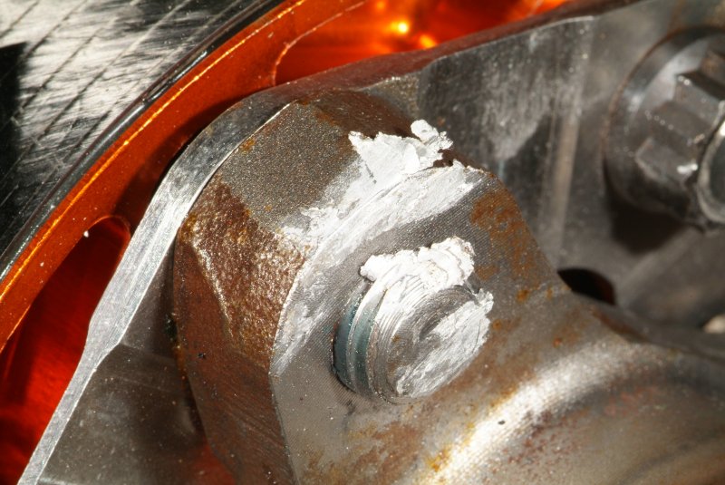
There were two bolts missing on the left side of the bell housing, and a third one on that same side there that I found sticking out a quarter of an inch. So there really was nothing at all holding the bell housing to the block on that side. Why is the bell housing bolted down in the first place? To keep it from moving. So with the bolts missing or loose on one side of the bell housing, what could happen? Well, it could MOVE. At least on the driver's side. Think about what happens when your rear tires break loose when you get on it. The rear end slides right, which means the torque would tend to want to move the drivetrain to the right. Why are there three bolts on the left side (driver's side) and only two on the right side? Quite likely because that is where the extra holding power of the extra bolt is needed. Without those bolts being there, what would happen? Yeah, that side of the bell housing would flex off of the block.

So what would happen if the bell housing COULD move? Well so could the front of the torque tube and driveshaft. But what would happen then? Well, the input shaft of the driveshaft slides into the pilot bearing in the crank. It also rides through both of the clutch disks which are turned by the splines in the center of those disks that mate with the splines of the input shaft going through them.

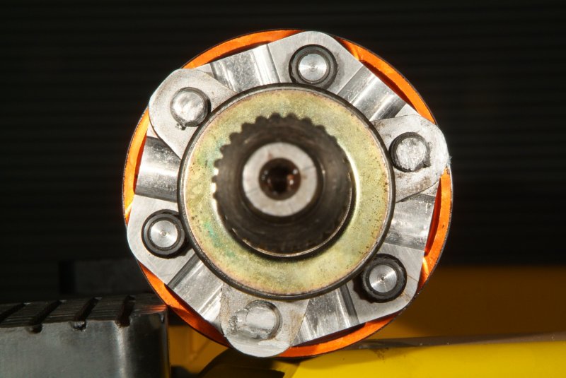
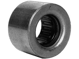
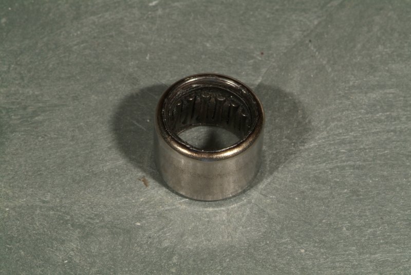
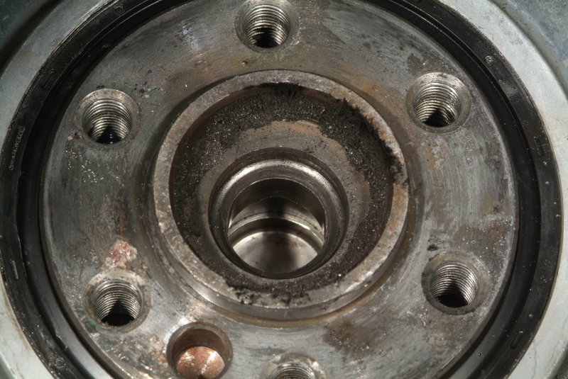
Here's a pic of one of the clutch disks showing those splines and how they should appear.


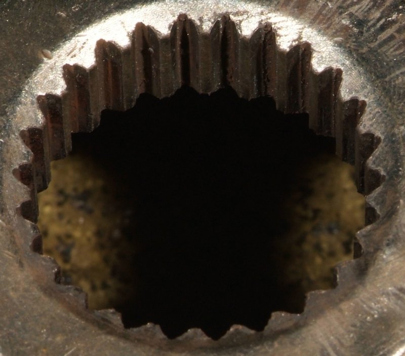
Notice the nice flat undamaged mating surfaces in the splines that would mate with the splines of the input shaft going through it.

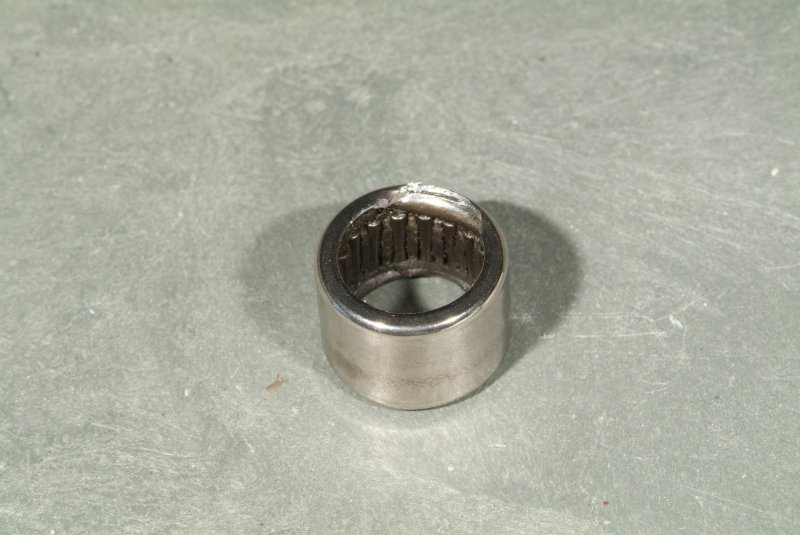
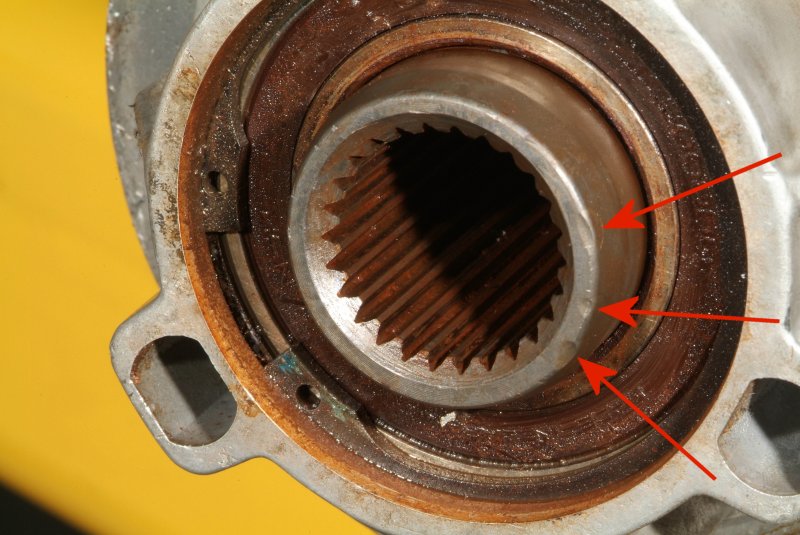
But look at the splines on this clutch disk.


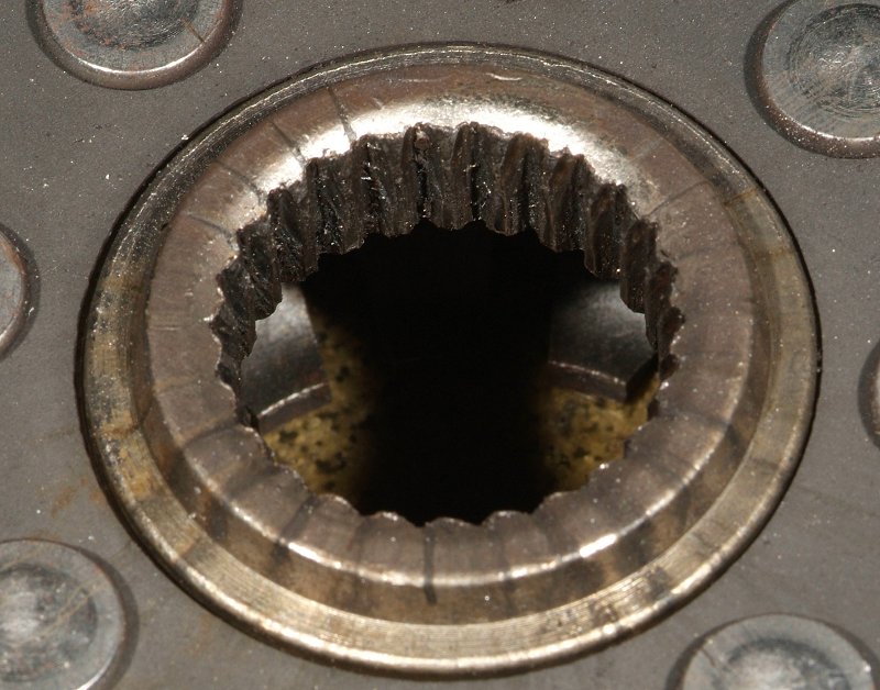
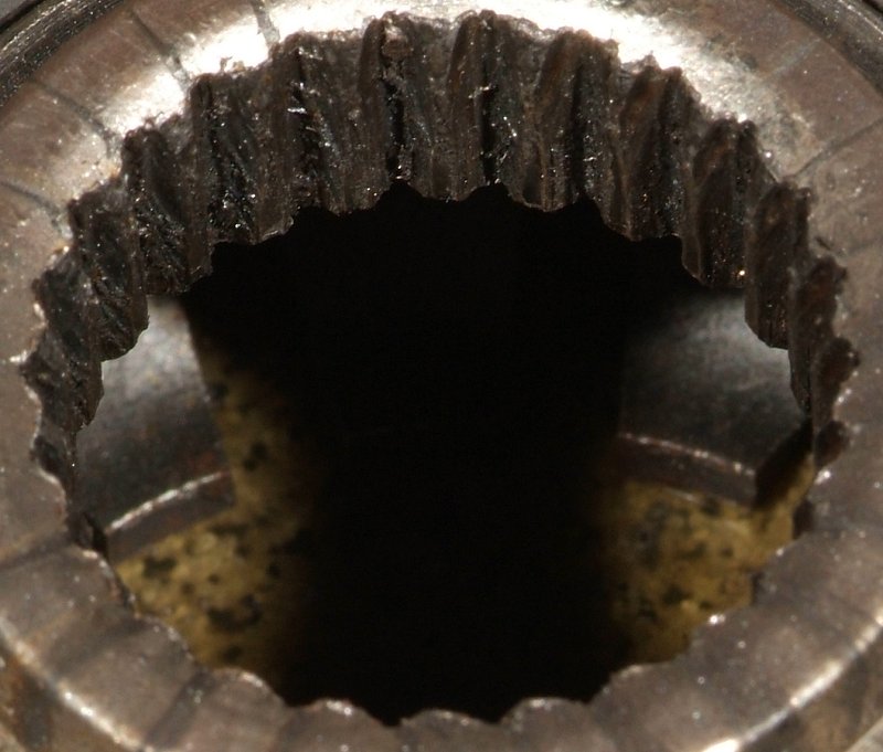
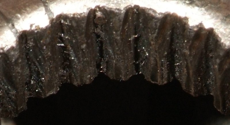
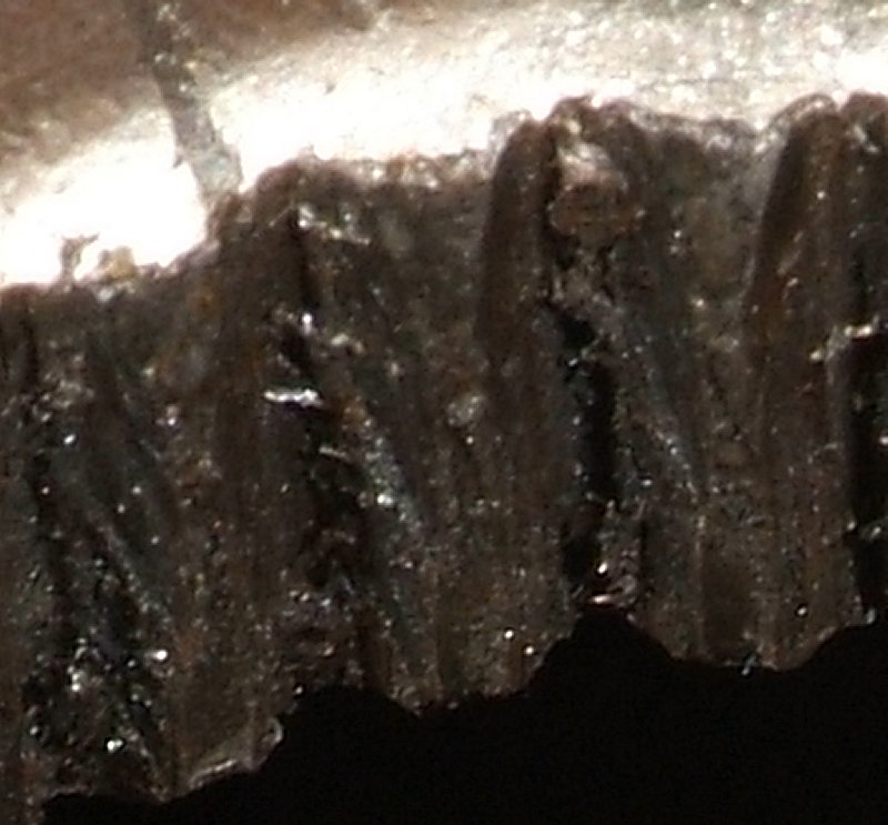
Notice the diagonal cuts across the splines. There is ONLY one thing that could do that, and that would have to be the splines on the input shaft going through the disk making those cuts. Which would have to mean that somehow that clutch disk was not perpendicular to the input shaft, so the input shaft's splines cut INTO the matching splines in the clutch disk.

Furthermore, I would speculate to say that there is a damned good chance that the disk got JAMMED onto that input shaft. And if that happened, what would be the result? Well, when releasing the clutch to close the pressure plate upon the disks, what would happen? If that disk were jammed on tight enough, it would PULL on the input shaft towards the flywheel. How much force is a clutch pressure plate exerting now on the driveshaft trying to pull it forward? Probably more than whatever it is in the torque tube that is designed to keep the drive shaft from moving forward was designed to handle.

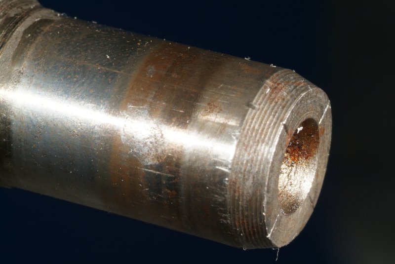
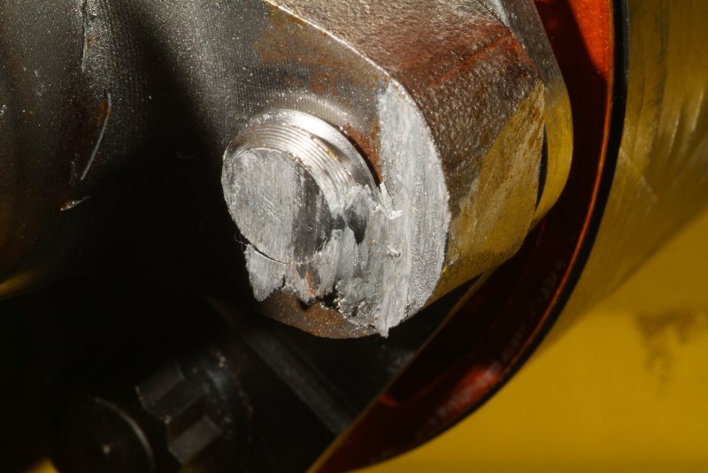
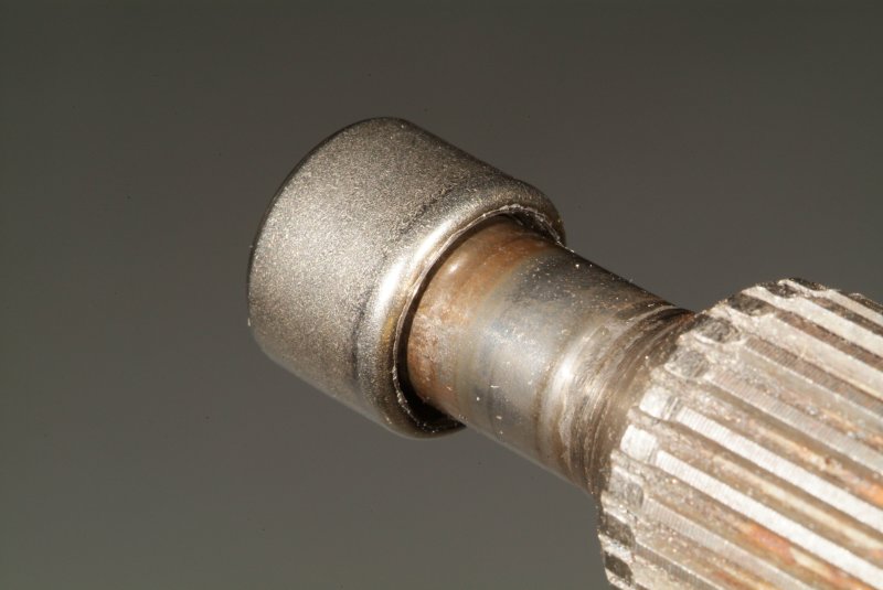
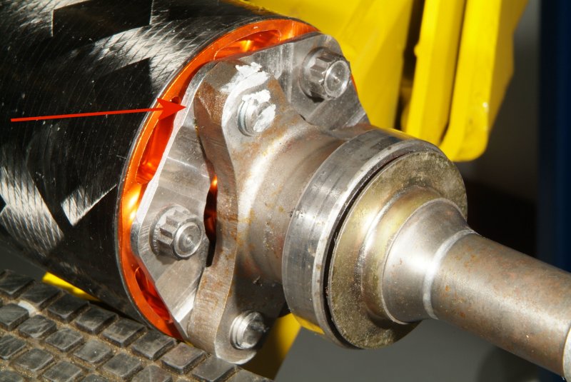
So what happened when the drive shaft got pulled forward enough to drop the input shaft bearing out of the front of the torque tube? Well, there would likely have been movement of the shaft inside of the throwout bearing/slave cylinder. And it appears that there are scuff marks and some minor damage there. Perhaps this contributed to the slave cylinder finally failing completely.


Shane mentioned to me that he had to use a very large pry bar and nearly bend it out of shape to get the torque tube separated from the bell housing. My guess is that the clutch disk was jammed solidly onto the input shaft of the drive shaft then.

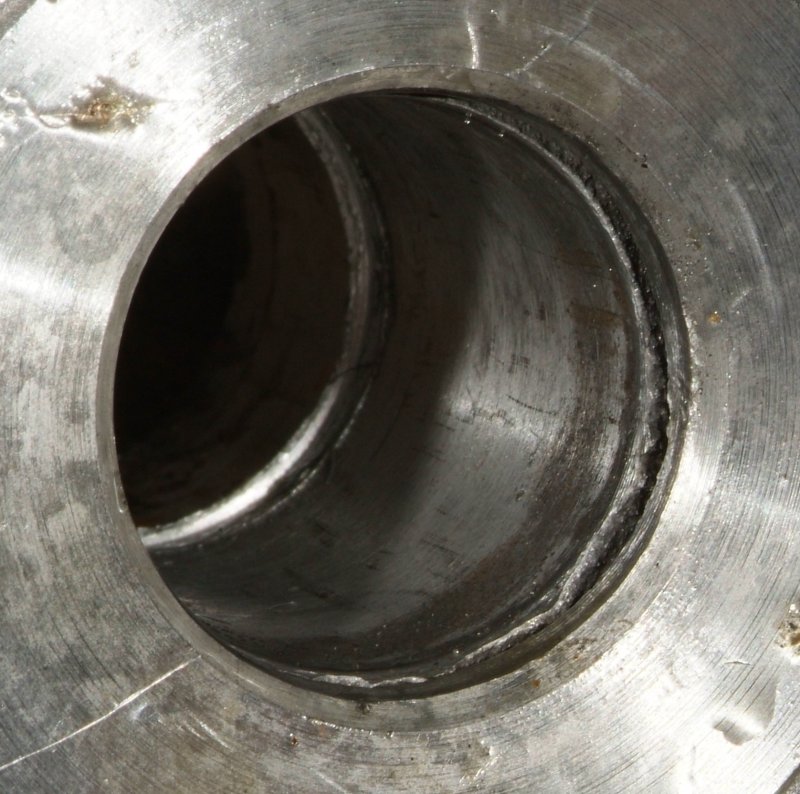
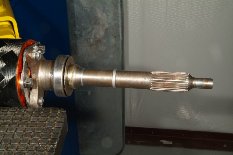
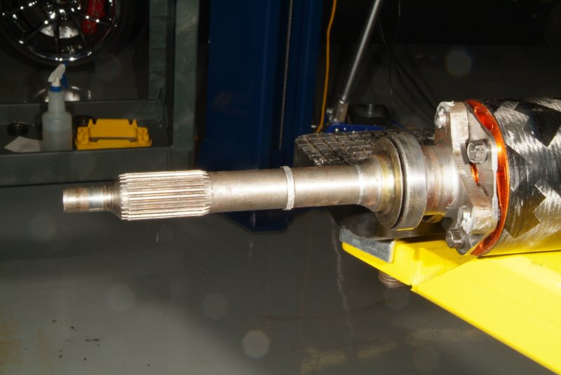
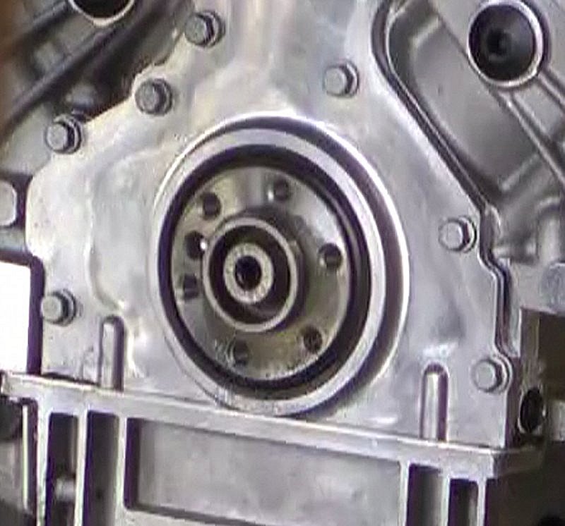
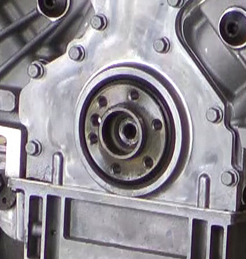
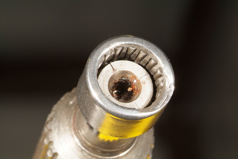
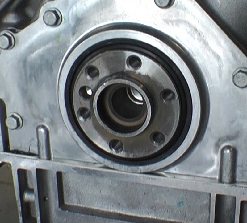
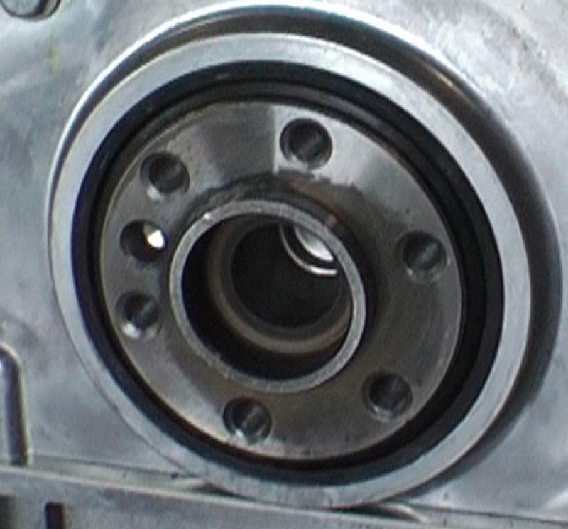
What about the pilot bearing itself if the drive shaft was going at an angle and moving in and out of the bearing? Well, does it look like the shaft remained at one place in the bearing in this picture?


I believe I see multiple areas where the shaft was seating into the pilot bearing which indicates that the shaft did not remain at the same depth within that bearing.

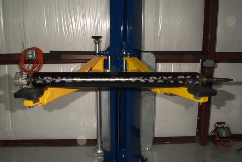
So, that's my speculation about the probable smoking gun in all this. My opinion is that the missing and loose bolts on the bell housing actually caused all of the damage now seen in the drive train. The clutch disk shows clear evidence that the splines in it were not lined up to mate to the input shaft splines, showing obvious damage as a result. It shows that the shaft had clearly cut into those disk splines at an angle. There really isn't anything I can see that could press against the back of the driveshaft to PUSH it through the torque tube. If the driveshaft was too long, then how did it get seated into the torque tube in the first place? I watched Chris Harwood install that carbon fiber drive shaft into the torque tube, and no way he used any sort of exceptional force to do so. Just a couple of light raps with the handle of a dead blow mallet and that was enough. So this seems to rule out PUSHING against the driveshaft, which only leaves PULLING on it from the front. And what is the only thing that could do that? The clutch pressure plate via the clutch disks.

There is still some gray area, of course. Was that loose bolt gradually loosening up on the bell housing while the car was being driven, and the damage started taking place at a certain point until it had a sudden complete failure? Did the slave cylinder fail coincidentally or was it sustaining damage that caused it to fail? What is it exactly that holds the driveshaft from moving forward in the torque tube and how much force does it take to BREAK that function? As far as I can figure out, the clutch is the only thing that has enough power to do that, and the only way it could do that is by PULLING on the shaft via a jammed clutch disk on the shaft. But was the disk intermittently jamming on the input shaft or has it been jammed on there for a while? I'm thinking it had to be happening intermittently making the noises I heard intermittently. But it could have been jammed on, but only sometimes became cocked at an angle enough to make noise. Probably no way to know for certain.

That might also explain the weirdness of the clutch action I experienced. When I would slowly release the clutch pedal, I could feel something grab ever so slightly and the car would start slowly moving. Releasing the clutch further did not increase the grab until nearly at the top of pedal travel, where it would finally grab completely.

Certainly all guess work based on the evidence I can actually see. Any maybe right or maybe wrong. But so far, it's the only thing that actually FITS the evidence with my limited knowledge of everything involved.

Sheesh, but do I have a splitting headache now. I just might have to break into my remaining dwindling supply of Excedrin Migraine pills..
__________________
Rich Z is offline   Reply With Quote
Unread 07-31-2012, 07:02 PM   #1768
Rich Z
Internet Sanitation Engineer
 
Rich Z's Avatar
 
Join Date: Mar 2006
Location: Crawfordville, FL
Posts: 15,127
Name : Rich Zuchowski
Rich Z will become famous soon enoughRich Z will become famous soon enough
Default

I just got off the phone after talking with Shane. He said he talked to Bryan at LME because apparently he was just as confused as I was about what he was seeing in the crankshaft. He had a C5 and a C6 pilot bearing in hand, and just didn't make any sense with what he was seeing. So he just asked Bryan if there was anything unusual about that engine concerning the crank, and which bearing it is supposed to have in it. Bryan told him the C5 stock bearing is what is needed, so Shane then knew that there was still part of that old one sitting in there. So he'll be tackling that tomorrow. The new clutch and torque tube/driveshaft are in so when he gets the pilot bearing/bushing issue straightened out, he should be able to start putting it all back together.

BTW, does anyone know if those aluminum colored plates on the front and back of the Pfadt carbon fiber driveshaft are optional? Are they used for spacing purposes and can be used on not used based on the length requirements of the entire driveshaft? Or are they a necessary element for all applications?


I still haven't heard a word from Pfadt about those dimensions I sent them. Sent them yesterday evening and then sent a followup email today and haven't gotten a reply.
__________________
Rich Z is offline   Reply With Quote
Unread 08-01-2012, 08:39 AM   #1769
shakedown067
Sinister C4
 
shakedown067's Avatar
 
Join Date: Jan 2007
Location: Largo, FL
Posts: 1,223
Name : Eric G
shakedown067 is on a distinguished road
Default

Mmm, I had a nice little write up until I was checking out LG's carbon driveshafts. I guess they are all different, and you'll have to wait to hear from Phadt. I think they are needed though.
shakedown067 is offline   Reply With Quote
Unread 08-01-2012, 09:17 AM   #1770
navy2kcoupe
!ereH nI depparT m'I pleH
 
navy2kcoupe's Avatar
 
Join Date: Jan 2007
Location: 25 miles south of Boston, MA. Also have a house in Dunedin FL.
Posts: 1,927
Name : Andy Anderson
navy2kcoupe has disabled reputation
Default

Rich, one thought comes to mind here about the "spacers". Notice how they thin out in between the bolts? I'm wondering if this is a design feature to allow the "spacer" to self destruct before the shaft gets wiped out under extreme torque situations? Not having any knowledge of torque tubes, carbon fiber driveshafts, or anything associated with them, its only a wild guess on my part. I would imagine that if it was used to adjust the length of the shaft, there would have been a bunch of them varying in thickness. Guess you will really have to wait to see what Phadt has to say about it. Good luck !
Andy
__________________
Andy Anderson - PROUD-VIETNAM-VETERAN.
VIETNAM VETERANS CORVETTE CLUB - FOUNDING MEMBER #1
https://sites.google.com/site/vietna...scorvetteclub/
navy2kcoupe is offline   Reply With Quote
Reply

Tags
427, aaron scott, chris harwood, rhs block, south georgia corvette, xtrememotorsports


Currently Active Users Viewing This Thread: 3267 (0 members and 3267 guests)
 

Posting Rules
You may not post new threads
You may not post replies
You may not post attachments
You may not edit your posts

BB code is On
Smilies are On
[IMG] code is On
HTML code is Off
Forum Jump

Similar Threads
Thread Thread Starter Forum Replies Last Post
bits of nitrous info grumpyvette Tech and How-To Articles 5 11-24-2008 04:02 PM
Decoding a Corvette's V8 Casting Numbers and Engine Stamps RSS Feed Corvette News Feeds 0 12-11-2007 10:26 AM
Removing The Engine From A C5 Corvette - Removal Procedures Part: 1 RSS Feed Tech and How-To Articles 0 10-04-2007 01:05 AM
Building A 427 For Today's World RSS Feed Tech and How-To Articles 0 10-04-2007 01:05 AM
New for 2008 - LS3 Motor with 430 HP! DocDye TAMPA BAY VETTES CLUB 0 04-29-2007 04:45 PM


All times are GMT -4. The time now is 08:08 AM.


Powered by vBulletin® Version
Copyright ©2000 - 2024, Jelsoft Enterprises Ltd.
Page generated in 0.08425307 seconds with 12 queries
All material copyrighted by CorvetteFlorida.com and
the respective owners of the material posted.