
|
| Maintenance, Mods, & Tips Mods | Tips | Repairs & Troubleshooting |
 |
|
 04-22-2012, 04:49 PM
|
#1501
|
|
Internet Sanitation Engineer
Join Date: Mar 2006
Location: Crawfordville, FL
Posts: 15,127
Name : Rich Zuchowski
|

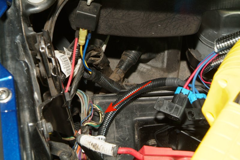
Been over in the garage poking around on the wiring harnesses in the battery compartment trying to figure out where I need to grab that voltage wire for the relay. Ed told me it would be a gray wire, and apparently there are a few gray wires in all those wire harnesses under there. But I did find a spliced wire, however it is on a BROWN wire.
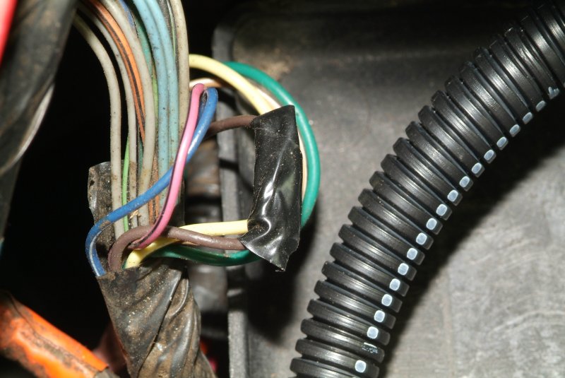

I send the pics to Ed, but he said this probably isn't what I need.
I did find a gray wire, but there isn't any splice on it, and I'm not real crazy about just stripping insulation off of wires helter skelter...
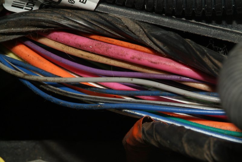
So I decided to look for the original STS manual and hope I could still read it, as it good pretty screwed up being oil soaked or something while at Harwood's shop. And yeah, I found it and could read most of the pages. Come to find out that the newer manual STS sent me has a completely different wiring arrangement and harness in it. Great.... The old manual says that you need to open up the fuse box to get UNDERNEATH it to splice into the gray wire there. So I popped the hold down clips on it and lifted the fuse box, and sure enough, there is a spliced gray wire there.
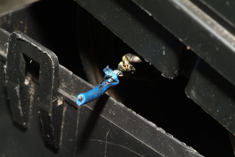
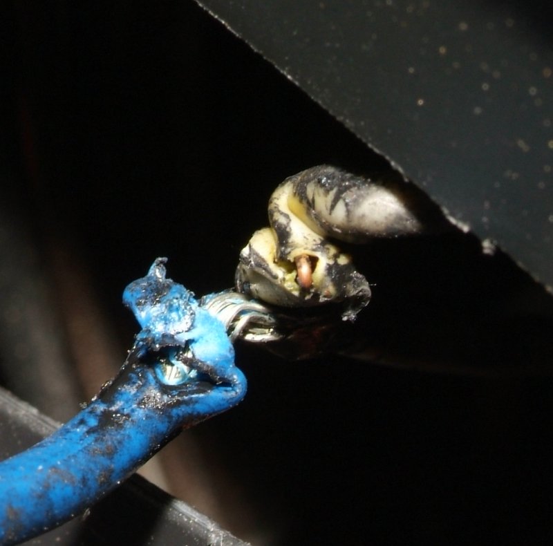
However the manual says that a BLUE wire should go to it, and now the blue wire from the relay goes to ground.
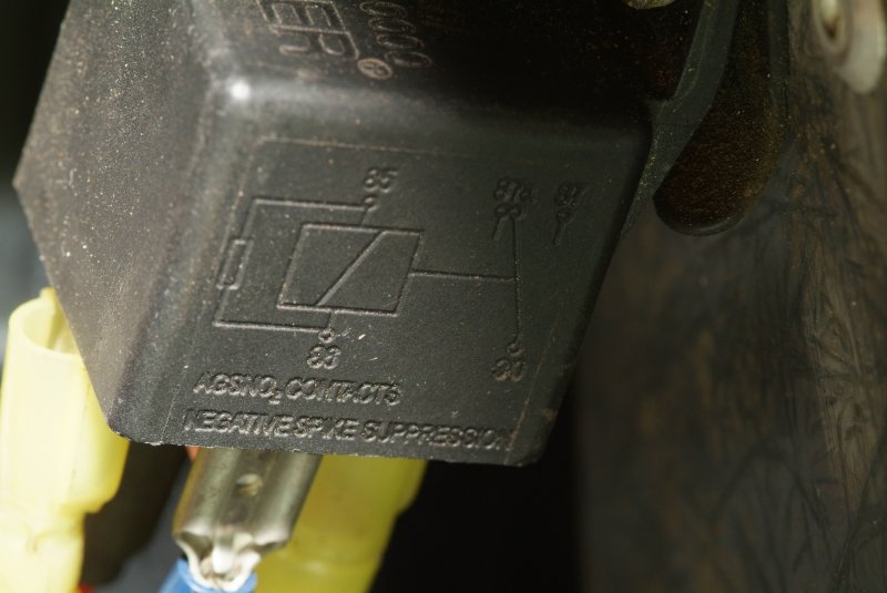
I took a pic of the relay, as there is a connection diagram of sorts on the side of it, but honestly, it doesn't mean a whole lot to me.
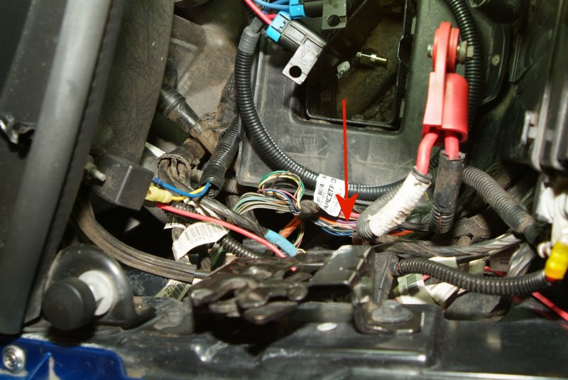
So anyway, I'm thinking that maybe all I need to do is to solder a wire back onto that gray wire under the fuse box, then connect that wire to where the red wire on the relay now connects to the top of the fuse box in a fuse slot.
Man, when I hook the battery back up and turn on the ignition again, this REALLY IS going to be a smoke test. 
__________________

|

|

|
|
04-22-2012, 05:42 PM
|
#1502
|
|
Sinister C4
Join Date: Jan 2007
Location: Largo, FL
Posts: 1,223
Name : Eric G
|
Yeah i agree on the relay. Typically I believe they use blue as a signal wire (audio installs) which is probably what the manual is referring to, but the installer could have used any color. I think you are on the right track. Good news is, if it happens to be wrong, you'd just need to replace the relay, but I think it'll work as you've described.
|
|
|
|
|
04-22-2012, 05:46 PM
|
#1503
|
|
Internet Sanitation Engineer
Join Date: Mar 2006
Location: Crawfordville, FL
Posts: 15,127
Name : Rich Zuchowski
|
I got the wire soldered onto that remnant of the blue wire spliced into the gray wire. I really couldn't do much about cleaning up that original solder job, but since I didn't have any problems in the past with the scavenge pump mysteriously dropping out, hopefully the joint is still good. I used to repair computer circuit boards in my younger days and learned how to make a GOOD solder joint. Something I have seen a lot of people fail to do properly.
Anyway, I ran the new wire through the STS wiring harness up to the relay and put a connector on it to mount to the relay. But I'll test it first when my battery gets charged up to make sure it is the correct wire I need.
Hopefully that will fix the problem with the power going to the scavenge pump for me.
__________________
|
|
|
|
|
04-22-2012, 09:29 PM
|
#1504
|
|
Member
Join Date: Jan 2010
Location: Boston Georgia
Posts: 213
Name : BENJAMIN LONG SR.
|
85 & 86 are just the energizing signal wires, one goes to ground, the other goes to the switching source. there is no right or wrong on which one goes to ground and power though I usually apply power to pin 85 and ground to pin 86
the same with 30 and 87. theoretically either one can be connected to the power source and the other to the pump. Conventionally 30 would be the power source (battery or fuse box) and 87 would be to the fuel pump as it has no power (normally open) until the circuit is energized. 87a only has power when the relay is not energized (normally closed).
It is true that the blue is commonly the signal wire source BUT if a red wire was used it could confuse someone to think that the blue was a ground.
In 120VAC wiring in newer appliance and tools and such there is a brown (hot) and blue (neutral) wires. So that could cause some confusion, not saying that is the case, just throwing that tidbit of info out there.
__________________
Life is hard. It's much harder when you're stupid.
|
|
|
|
|
04-23-2012, 12:47 AM
|
#1505
|
|
Internet Sanitation Engineer
Join Date: Mar 2006
Location: Crawfordville, FL
Posts: 15,127
Name : Rich Zuchowski
|
Actually I did use a red wire as the signal wire, since that is what I had handy at the moment. I really didn't see the need to run out and buy some blue wire. I couldn't use the existing blue wire as it was cut too short when it was then run to a ground lug, to run it back to the gray wire splice under the fuse box. So I made do with what I had. Besides, this can't be that much worse than having TWO blue wires, I guess. One to signal and the other to ground.
Besides, I'll probably be the one working on this sort of stuff on my car from here on out........ I'll just have to make up a revised diagram so I can refer back to it when my memory is hazy about the details.
Thanks for the explanation. I was hoping someone would know something about that type of relay.
__________________
Last edited by Rich Z; 04-23-2012 at 01:40 AM.
|
|
|
|
|
04-23-2012, 01:38 PM
|
#1506
|
|
Internet Sanitation Engineer
Join Date: Mar 2006
Location: Crawfordville, FL
Posts: 15,127
Name : Rich Zuchowski
|
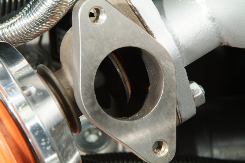
Sheesh.... The guy I ordered the replacement throttle body from seems to be just dragging his feet getting it out the door to me. He said he was just finishing up on polishing a unit back on April 7, but here it is April 23rd and I STILL don't have it. 
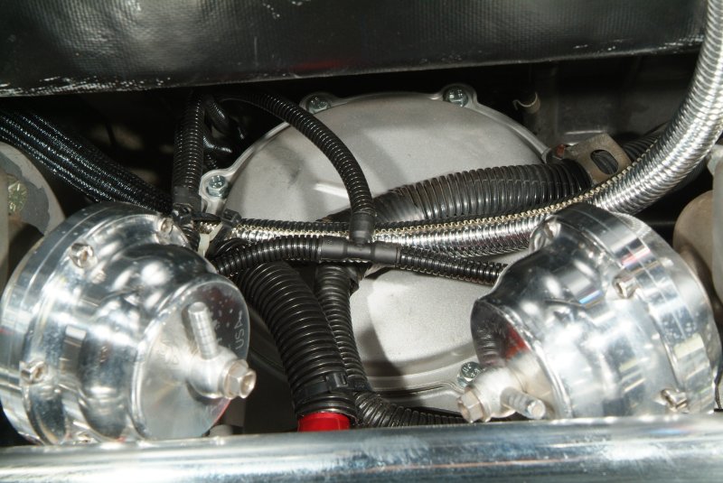
And STS says that the wastegates should NOT be plugged at those vent ports. I thought Aaron knew turbo systems, so I'm trying to find out what sort of legitimate reason someone would plug those vents up for so I can try to understand WHY he did that. 
As for the wiring issues, they want to sell me a new wiring harness, but I seriously doubt a new harness is going to match up with what I have on the car now anyway. So I need to find out if what I have can be made to WORK without throwing even more money at it. If it will work with the wiring now in place, then that is what I want to do. 
__________________
|
|
|
|
|
04-23-2012, 02:06 PM
|
#1507
|
|
Sinister C4
Join Date: Jan 2007
Location: Largo, FL
Posts: 1,223
Name : Eric G
|
I'd work with the wiring harness you have too. But if I was a sellsman, I want you to buy a new one too! Have you tried unplugging those vent ports? What the hell is in there. Looks like putty to me.
|
|
|
|
|
04-23-2012, 04:27 PM
|
#1508
|
|
Internet Sanitation Engineer
Join Date: Mar 2006
Location: Crawfordville, FL
Posts: 15,127
Name : Rich Zuchowski
|
Quote:
Originally Posted by shakedown067

I'd work with the wiring harness you have too. But if I was a sellsman, I want you to buy a new one too! Have you tried unplugging those vent ports? What the hell is in there. Looks like putty to me.
|
Yeah. Connie helped me put a test light on the wire I soldered in to that gray wire underneath the fuse box and it is cycling power properly now. Lights up when the ignition key is turned on, then goes off after 2 seconds. So I pulled the wire running to the fuse box at the top of the fuse box and the relay and put the new wire on the relay terminal. Interestingly enough, when I was looking to see which of the two fuses I need to put BACK into the fuse box itself (it was plugged into the O2 sensor fuse socket) the fuse diagram calls for a 15 amp fuse, but Aaron put in a 20 amp fuse instead. So I put the correct 15 amp fuse in there as it called for.
I think this will work now, as needed. There used to be a large resistor in that harness somewhere that I remember seeing, but Ben says that was used to allow a switch (which is also no longer there) to be able to select a low and fast speed setting for the scavenge pump. He says all the newer kits have eliminated that resistor and run only at the fast speed.
I still need to check on the alarm buzzer that is supposed to be connected to the pressure switch. This is supposed to trigger that alarm if the switch detects 3 lbs or more of pressure. I know it didn't work when I had a scavenge pump failure a while back, so I'm not sure if it was ever hooked up correctly.
Still trying to figure out the wastegate situation with STS's help. Ben says that having those vent ports plugged will cause the turbos to go into an overboost condition and is NOT a good idea. So I'm curious about how Aaron got the 10 lb springs he said he put into the wastegates to actually give the correct boost readings. Does anyone know how I would check those wastegate springs and whether they are marked in any way to tell me their ratings?
Oh yeah, when I was trying to hook up the battery via jumper cables to test with the test light, I had to find a way to tighten up the battery bolts that connect the battery cable to those side mounts on the battery. I figured I would just use those gold plated mounts that came with my Racetronix harness for the fuel pump so I could more easily find a correctly threaded nut. Wrong! The thread on those gold battery terminal fittings do not match the threads in the battery itself. WTF?  So I guess they won't fit in those top post adapters I ordered neither. So I have to wonder WHERE exactly they are supposed to screw into?
Yeah, just popped yet another Excedrin...... I know this is all just small stuff, but sheesh, give me a FRIGGIN BREAK.....
__________________
Last edited by Rich Z; 04-23-2012 at 05:24 PM.
Reason: Word should have been "on" instead of "off"
|
|
|
|
|
04-24-2012, 12:40 AM
|
#1509
|
|
Internet Sanitation Engineer
Join Date: Mar 2006
Location: Crawfordville, FL
Posts: 15,127
Name : Rich Zuchowski
|
Been ending emails back and forth with Ben Brownie at STS about my turbo system. I explained what I did with the wiring and he says that will work fine.
As for the wastegate situation, well, that isn't so fine. He says the plugged rear vent ports will push the turbos into an overboost situation. Meaning they will reach a higher boost than the springs in the wastegates are designed to allow before opening. He asked me to open up the wastegates and photograph the springs as they are supposed to be color coded and that will tell him what they are rated at and possibly tell us what sort of boost those plugged ports will really push the turbos to. Aaron told me that he put 10 lb springs in the wastegates but the boost was more like 8.5 lbs on the boost gauge. He said losses in the system caused the reduction, and I had asked him to put in springs that would give me a real 10 lbs at the intake, but I guess he didn't want to do that.
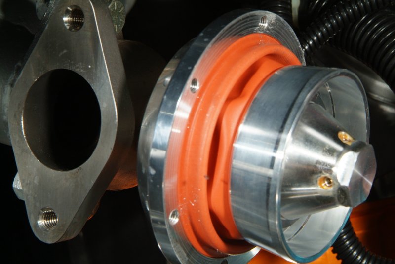
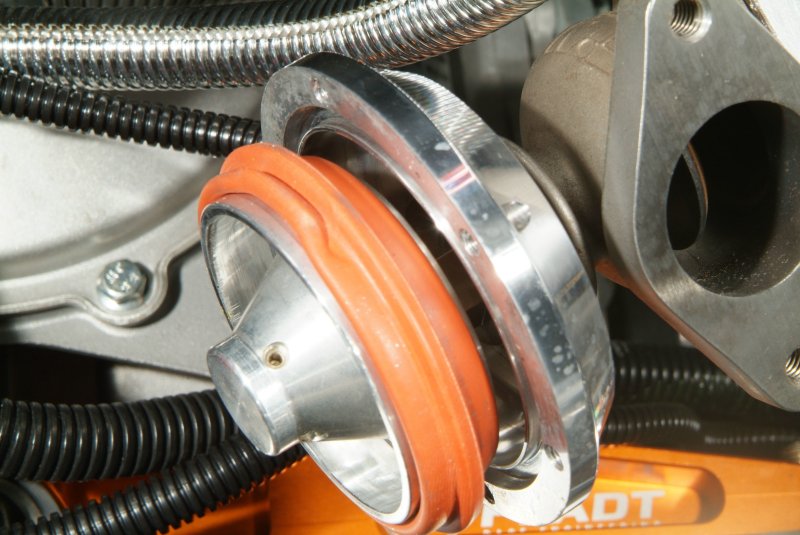
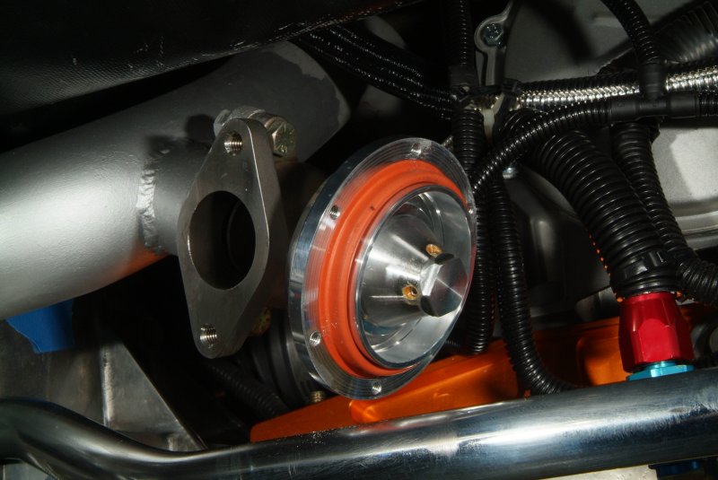
Anyway, I guess I'm glad I don't have stronger springs in those wastegates. The bolts holding the backplate on literally popped out in some instances from the spring tension. Had to scramble to find them all. And I was surprised at how simple of a mechanism a wastegate really is. Pretty much just like the fuel pressure regulator in design. If you've never seen the inside of a wastegate before (this is the first time I've ever seen it myself), well here's some pics.
First off Ben wanted to see what the vacuum connections looked like to make certain that were OK. I told him I traced the line at the T back to the back of the intake manifold near the MAP sensor.
So here's the springs when I pulled them out:
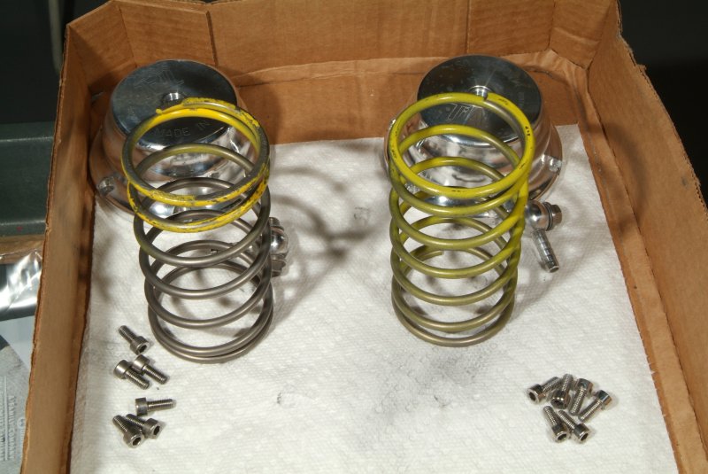
The spring from the original wastegate is on the left, and the one from the new wastegate that Aaron installed for me to put a wastegate on each exhaust side is on the right. I was surprised that the spring on the left was apparently so much more *used* looking than the one on the right. Maybe one side is activated more than the other? 
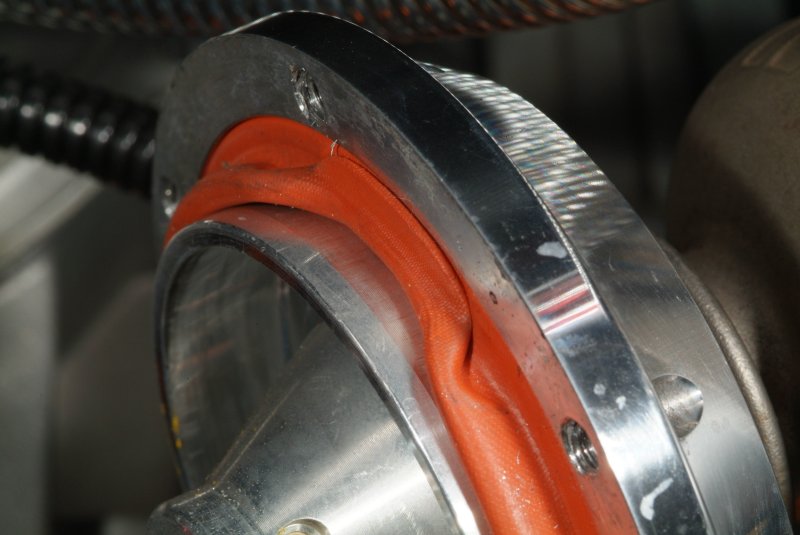
One thing that did disturb me was that when I took apart the older wastegate, the rubber seal inside was screwed up in that it apparently got caught inbetween the base and the cap when it was tightened down. I didn't see any breaks in it, but I hope I don't have to now replace the darn thing. I guess Aaron was a bit careless when replacing that spring in that side. I know if I ask STS about this they will say DEFINITELY that the wastegate needs to be replaced. But I'm going to see if I can find a new seal somewhere instead. It does seem to be bouncing back into shape since I uncrimped it and smoothed it out with my finger, though, so maybe it will be ok.
Anyway, here's a few more pics I took of the insides of the wastegates if anyone is interested in seeing them.
__________________
|
|
|
|
|
04-24-2012, 06:58 PM
|
#1510
|
|
Internet Sanitation Engineer
Join Date: Mar 2006
Location: Crawfordville, FL
Posts: 15,127
Name : Rich Zuchowski
|
I contacted Tial about that pinched diaphragm and they say it will be OK as long as there are no cracks or rips in the material. So I'll just have to be careful putting the wastegates back together.
Ben at STS says that the 10 lb springs are correct in the wastegates, and therefore having the rear vent ports plugged will cause the turbos to overboost, perhaps dangerously so in my opinion, if the car was tuned for a max boost of 10 psi. No one I have asked has been able to think of any logical reason why those ports were plugged up.
So I'll be cleaning out those ports as best I can and putting the wastegates back together again.
BTW, on another forum, the topic of how long my car has actually been down was brought up. So I went back and checked the dates, and here's what I came up with:
- 10/27/09 thru 09/17/10 at XtremeMotorsports in Blountstown, FL run by Chris Harwood. 325 days.
- 09/17/10 thru 11/18/11 at South Georgia Corvette in Thomasville, GA run by Aaron Scott. 427 days.
- 11/18/11 thru present sitting on the lift in my garage. 158 days and counting.
So actually this has been ongoing for 910 days, or about two and a half years all total.
__________________
|
|
|
|
|
Currently Active Users Viewing This Thread: 3079 (0 members and 3079 guests)
|
|
|
 Posting Rules
|
You may not post new threads
You may not post replies
You may not post attachments
You may not edit your posts
HTML code is Off
|
|
|
All times are GMT -4. The time now is 01:31 AM.
|


 Linear Mode

