• Got the Contributing Memberships stuff finally worked out and made up a thread as a sort of "How-To" to help people figure out how to participate. So if you need help figuring it out, here's the thread you need to take a look at -> http://www.corvetteflorida.com/forums/showthread.php?t=3581 Thank you, everyone! Rich Z.

427 engine (part 2) - RHS block

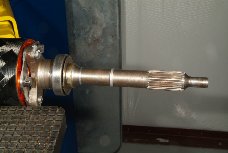
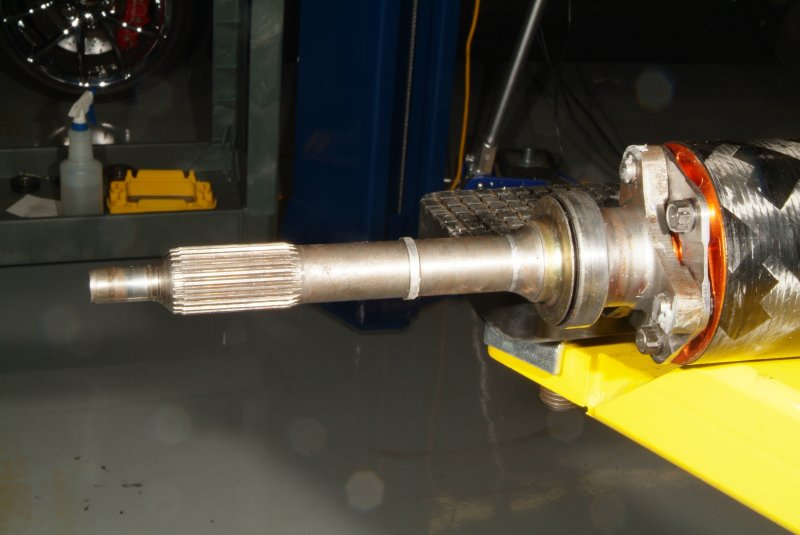
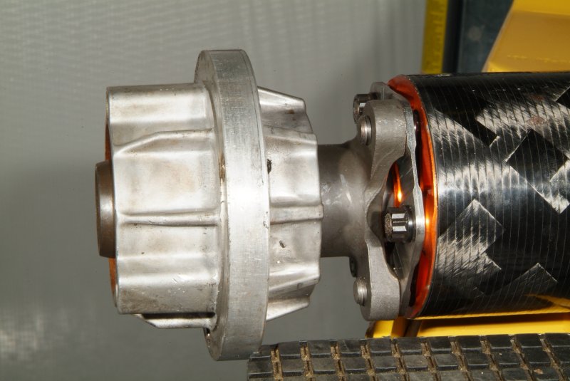
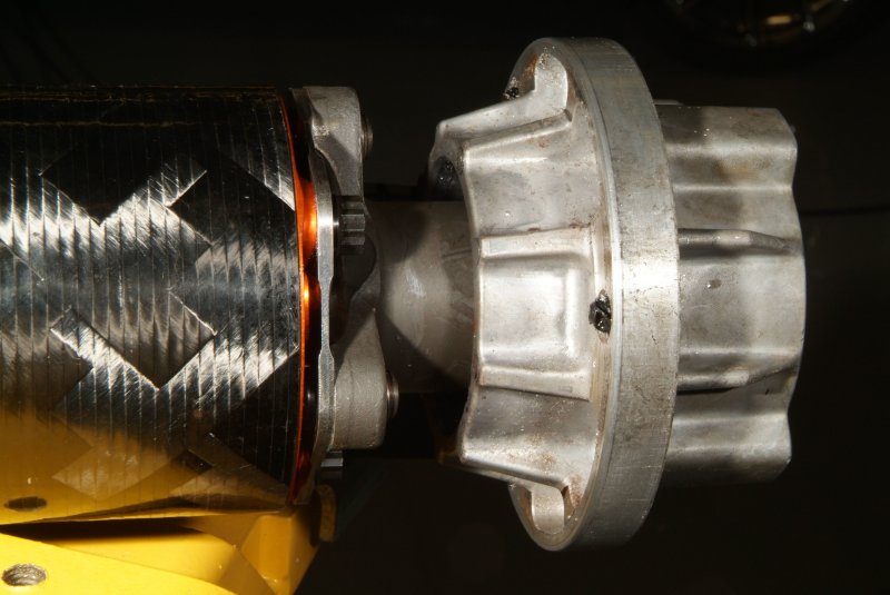
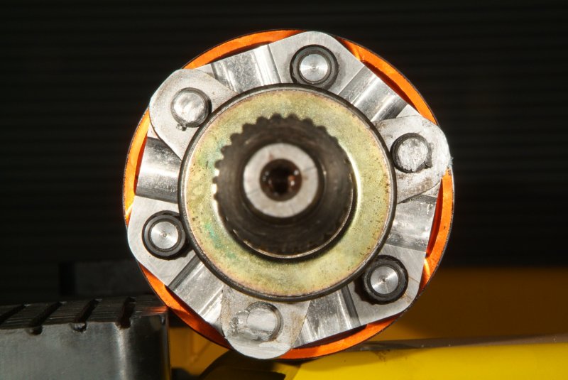
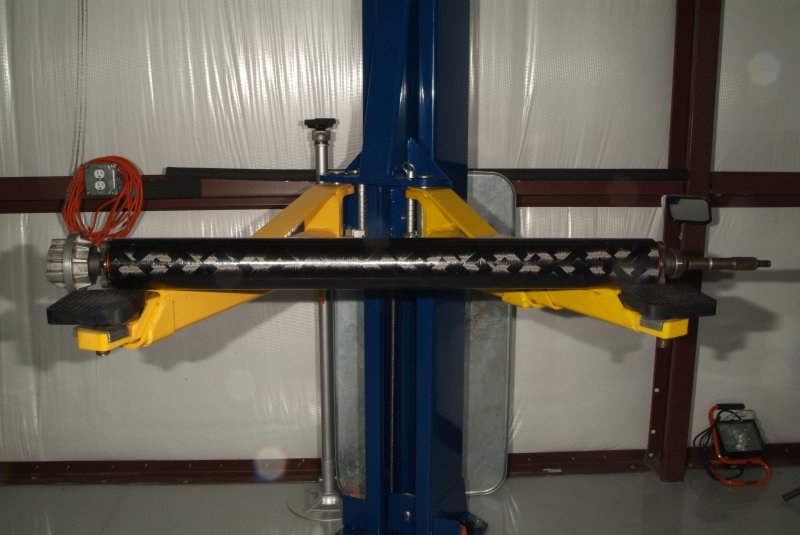
And here's some various pics I took of the driveshaft itself.

cf_driveshaft_01.jpg


cf_driveshaft_02.jpg


cf_driveshaft_03.jpg


cf_driveshaft_04.jpg


cf_driveshaft_05.jpg


cf_driveshaft_06.jpg


cf_driveshaft_07.jpg


cf_driveshaft_08.jpg


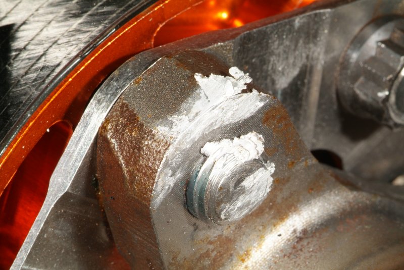
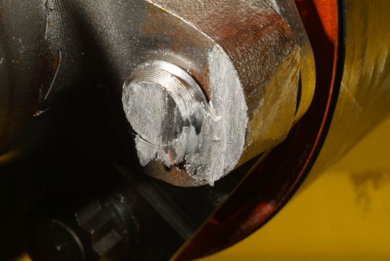
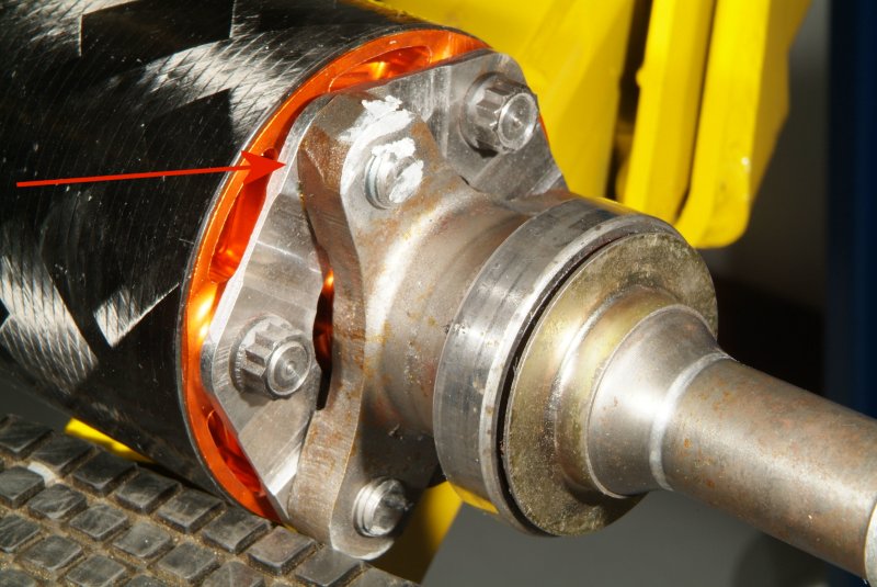
Notice the aluminum scraped onto the bolts holding the front input shaft onto the carbon fiber shaft. Obviously there was some substantial movement FORWARD of that shaft in the torque tube.
 
To further muddy the waters about what the heck happened, I brought home the pilot bearing that Shane pulled from my crank.

First off, here's a couple of pics that I captured from the video I took of Chris Harwood installing the pilot bearing while he was putting the clutch stuff together on my engine.

pilot_bearing_installed_01.jpg


pilot_bearing_installed_02.jpg


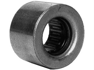
Now the following is what I found when just doing a Google search for a C5 pilot bearing..

c5_pilot_bearing_01.jpg


I would say that the bearing Chris Harwood installed looks pretty similar to the later picture.

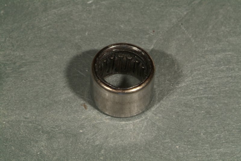
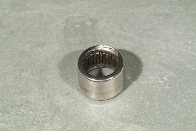
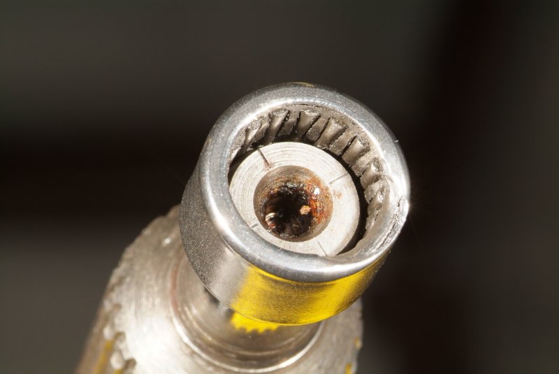
Now, here's some pics of the pilot bearing that Shane extracted from my crank..

pilot_bearing_11.jpg


pilot_bearing_12.jpg


pilot_bearing_13.jpg


pilot_bearing_14.jpg


**Just a note, that the damage you see on one side of the bearing happened when the bearing was extracted from the crankshaft.**

:confused:

I'm sorry, but I just don't know what to make of this. Was my pilot bearing changed out while at Aaron Scott's shop? If so, why does it look so different from what Chris Harwood originally put in there?
 
I guess what bugs me about this is that I feel that I need to find out if this driveshaft moving forward in the torque tube was the cause of everything else or, is it just another symptom of something else not found yet that caused that to happen. I don't feel like I have found the smoking gun yet.

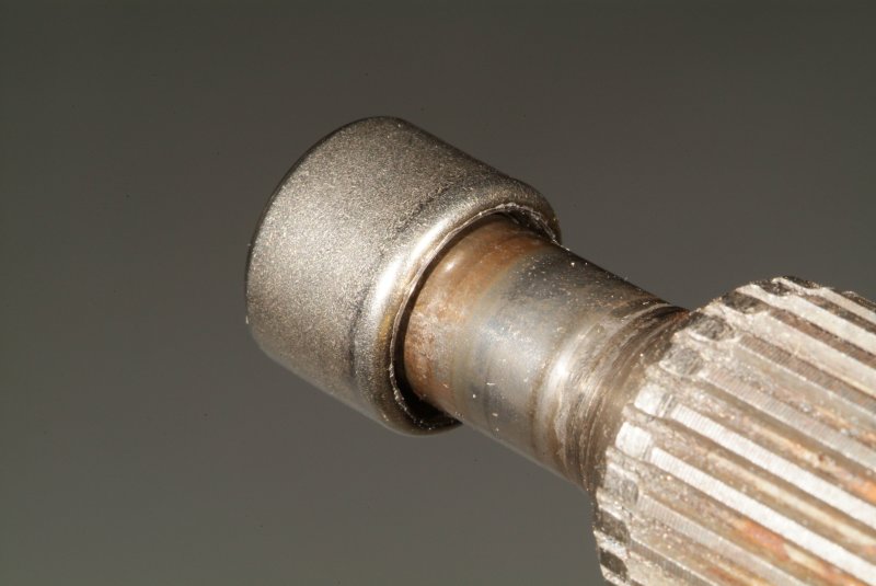
Another piece of the puzzle is shown here, I think.

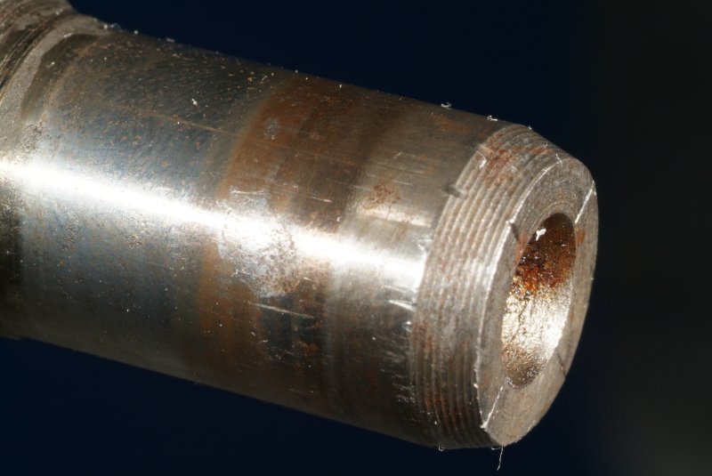
cf_driveshaft_09.jpg


Look at those marks on the shaft going into the spindle. It appears that someone beat pretty hard on it, evidently trying to shove it forward. So did whoever it was beat it hard enough to BREAK something, and that allowed the driveshaft to move forward in the torque tube?

:shrug01: That's what I am trying to figure out.

Also, what do you think the chances are that the bearing shown in the above photo is a brand new one like Chris Harwood told me was put onto that shaft? :rolleyes:
 
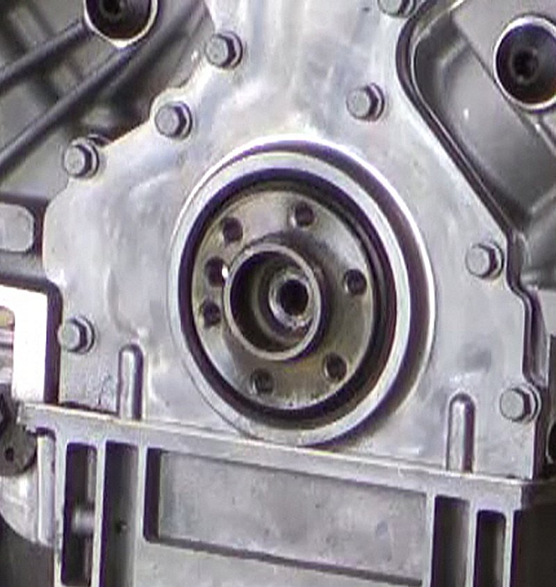
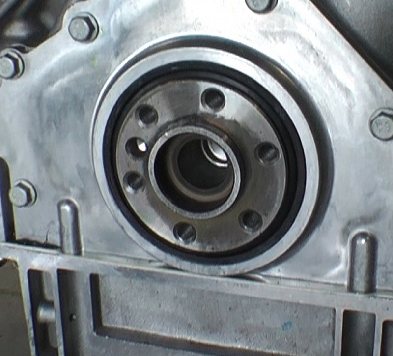
In reference to the above pics concerning the pilot bearing, I'm trying to resolve a conflict in my mind with what the heck I am seeing in the crankshaft.

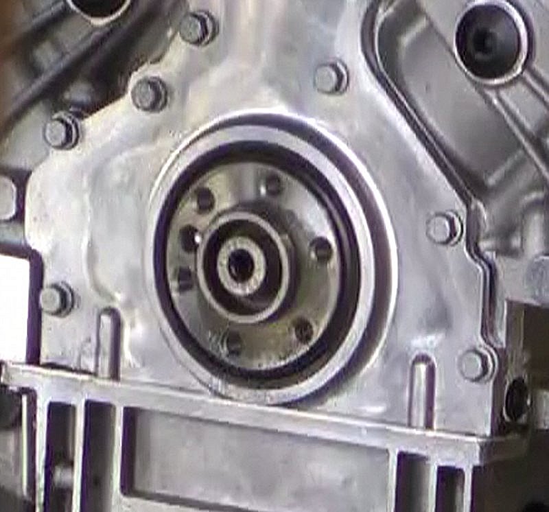
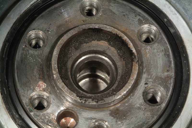
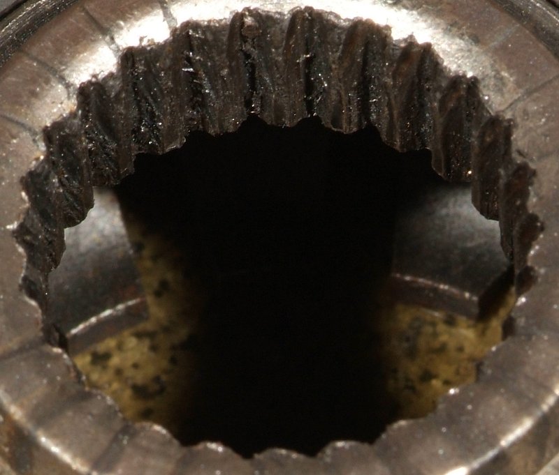
Here's a pic that I took of the crankshaft end as it exists now where Shane removed the pilot bearing.

crankshaft_19.jpg


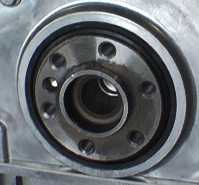
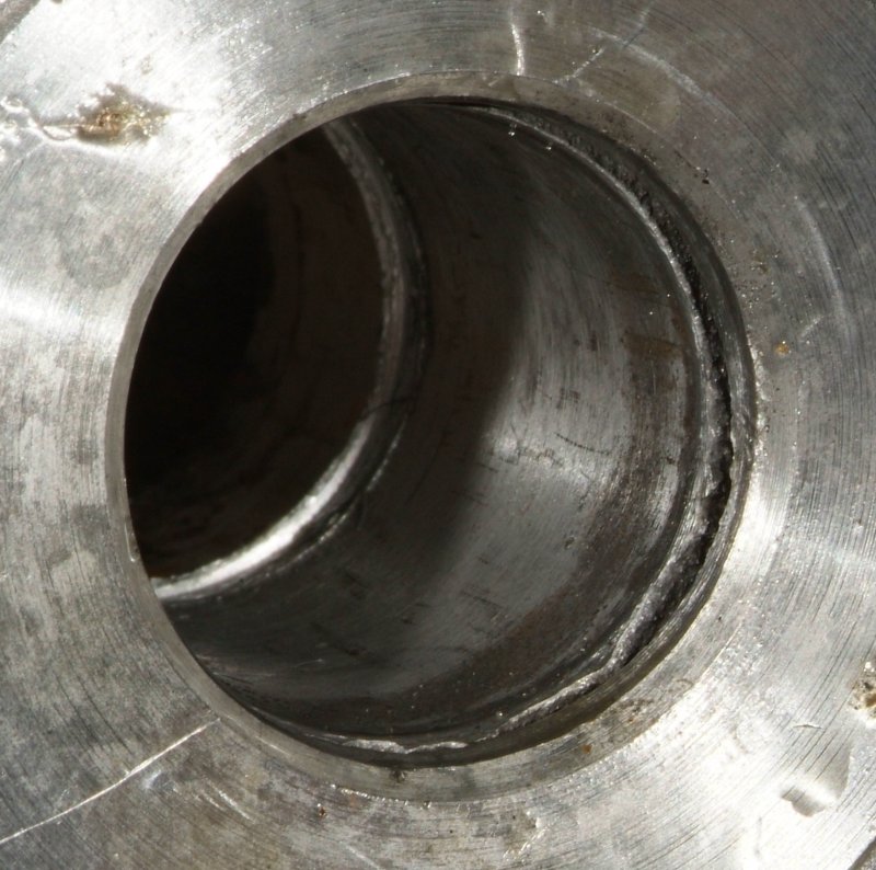
And here's a couple of pics that I captured from before Chris Harwood put that original pilot bearing into the crankshaft.

crankshaft_20.jpg


crankshaft_21.jpg


Man, I dunno, but the ONLY thing that makes sense to me when I look at these photos as well as the pilot bearing that Shane removed is that the outer shell of that pilot bearing is STILL in the crank. And it is that bearing shell that the drive shaft apparently bored into, NOT the crank itself. Look at that silver colored plug in the back of that hole. There is no way to get that thing in and out of there in the top pic, as is. The plug is the same diameter of the larger hole as shown in the bottom two pics. So obviously there is something in that hole now making it appear to be smaller than that plug is. It's either that part of that pilot bearing is still in there, which will then resolve the problem as to why the pilot bearing Shane removed is smaller than the one I show in pics of Chris Harwood installing, or I'm just losing my friggin' mind with this stuff.

Again, here's a pic of what the C5 pilot bearing is SUPPOSED to look like.
c5_pilot_bearing_01.jpg


Here's a pic of what Shane extracted.
pilot_bearing_11.jpg


Taking this all together, that brass looking outer shell of the actual bearing HAS to still be in there.
 
Hey Rich. It looks like the outer shell of the pilot bearing is still lodged in the back of the crank...I suggest you get ahold of a new pilot bearing for your car, and look at it closely to see if it can be seperated from it's outer shell?...
 
Hey Rich. It looks like the outer shell of the pilot bearing is still lodged in the back of the crank...I suggest you get ahold of a new pilot bearing for your car, and look at it closely to see if it can be seperated from it's outer shell?...

My guess is that the driveshaft bored the front section off of the bearing, which then allowed the center section to more easily be pulled loose from the outer shell. It would be very easy to miss since that bearing had to be hammered into place, and the boring action of the driveshaft would have obscured the seam of where the bearing fits into the hole. Heck, I've been staring at pictures of this ever since I first saw the crank with the center part of the bearing extracted trying to figure out what the heck I was looking at. It just didn't make any sense to me at all. When I started looking at the closeups of the bearing itself that I took yesterday, well then I could see a fine lip on the front of the bearing that looked chewed up. Then the pieces started falling into place. Once I went back and captured a picture of the crank opening itself before the bearing was installed by Chris Harwood, well that showed the hole pretty clearly then. Part of that bearing HAD to still be in the crank. Which is a GOOD thing, since it means that it wasn't actually the crank itself that got bored into as I had feared.

I swear this is driving me insane. I STILL haven't figured out why that driveshaft moved forward in the first place. I STILL don't know what really CAUSED all of this to happen.
 
Well, I think I've been looking at this from the wrong perspective concerning what caused the driveshaft to push through the torque tube. Maybe it didn't get pushed through at all. After all, what could actually do that? The transmission and differential? HOW? They are restrained by being bolted to the rear cradle which is bolted to the frame of the car. So I would have to say, no, not likely.

But suppose the shaft were PULLED forward? Now what could cause that?

Well let's look at the facts that have been found so far.

There were two bolts missing on the left side of the bell housing, and a third one on that same side there that I found sticking out a quarter of an inch. So there really was nothing at all holding the bell housing to the block on that side. Why is the bell housing bolted down in the first place? To keep it from moving. So with the bolts missing or loose on one side of the bell housing, what could happen? Well, it could MOVE. At least on the driver's side. Think about what happens when your rear tires break loose when you get on it. The rear end slides right, which means the torque would tend to want to move the drivetrain to the right. Why are there three bolts on the left side (driver's side) and only two on the right side? Quite likely because that is where the extra holding power of the extra bolt is needed. Without those bolts being there, what would happen? Yeah, that side of the bell housing would flex off of the block.

So what would happen if the bell housing COULD move? Well so could the front of the torque tube and driveshaft. But what would happen then? Well, the input shaft of the driveshaft slides into the pilot bearing in the crank. It also rides through both of the clutch disks which are turned by the splines in the center of those disks that mate with the splines of the input shaft going through them.

Here's a pic of one of the clutch disks showing those splines and how they should appear.
disk_undamaged_01.jpg


Notice the nice flat undamaged mating surfaces in the splines that would mate with the splines of the input shaft going through it.

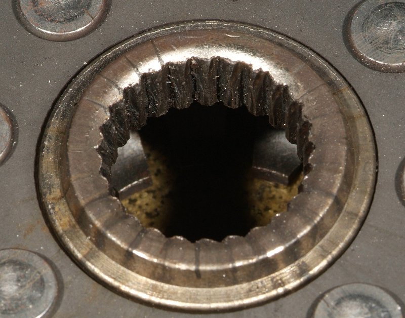
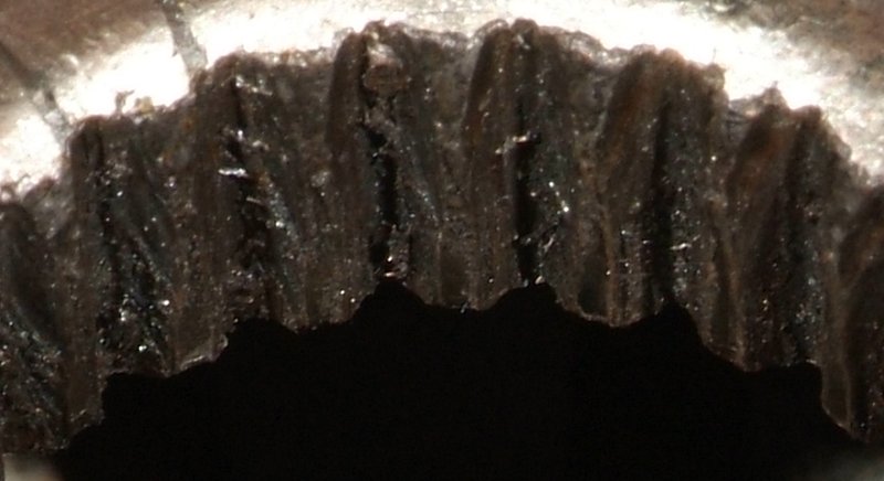
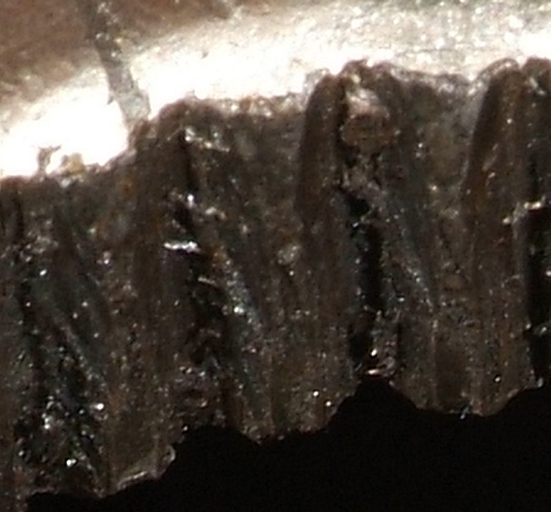
But look at the splines on this clutch disk.
disk_damage_01.jpg


disk_damage_02.jpg


disk_damage_03.jpg


disk_damage_04.jpg


Notice the diagonal cuts across the splines. There is ONLY one thing that could do that, and that would have to be the splines on the input shaft going through the disk making those cuts. Which would have to mean that somehow that clutch disk was not perpendicular to the input shaft, so the input shaft's splines cut INTO the matching splines in the clutch disk.

Furthermore, I would speculate to say that there is a damned good chance that the disk got JAMMED onto that input shaft. And if that happened, what would be the result? Well, when releasing the clutch to close the pressure plate upon the disks, what would happen? If that disk were jammed on tight enough, it would PULL on the input shaft towards the flywheel. How much force is a clutch pressure plate exerting now on the driveshaft trying to pull it forward? Probably more than whatever it is in the torque tube that is designed to keep the drive shaft from moving forward was designed to handle.

So what happened when the drive shaft got pulled forward enough to drop the input shaft bearing out of the front of the torque tube? Well, there would likely have been movement of the shaft inside of the throwout bearing/slave cylinder. And it appears that there are scuff marks and some minor damage there. Perhaps this contributed to the slave cylinder finally failing completely.

throwout_bearing_10.jpg


Shane mentioned to me that he had to use a very large pry bar and nearly bend it out of shape to get the torque tube separated from the bell housing. My guess is that the clutch disk was jammed solidly onto the input shaft of the drive shaft then.

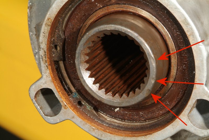
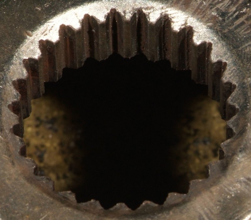
What about the pilot bearing itself if the drive shaft was going at an angle and moving in and out of the bearing? Well, does it look like the shaft remained at one place in the bearing in this picture?

input_shaft_end_01.jpg


I believe I see multiple areas where the shaft was seating into the pilot bearing which indicates that the shaft did not remain at the same depth within that bearing.

So, that's my speculation about the probable smoking gun in all this. My opinion is that the missing and loose bolts on the bell housing actually caused all of the damage now seen in the drive train. The clutch disk shows clear evidence that the splines in it were not lined up to mate to the input shaft splines, showing obvious damage as a result. It shows that the shaft had clearly cut into those disk splines at an angle. There really isn't anything I can see that could press against the back of the driveshaft to PUSH it through the torque tube. If the driveshaft was too long, then how did it get seated into the torque tube in the first place? I watched Chris Harwood install that carbon fiber drive shaft into the torque tube, and no way he used any sort of exceptional force to do so. Just a couple of light raps with the handle of a dead blow mallet and that was enough. So this seems to rule out PUSHING against the driveshaft, which only leaves PULLING on it from the front. And what is the only thing that could do that? The clutch pressure plate via the clutch disks.

There is still some gray area, of course. Was that loose bolt gradually loosening up on the bell housing while the car was being driven, and the damage started taking place at a certain point until it had a sudden complete failure? Did the slave cylinder fail coincidentally or was it sustaining damage that caused it to fail? What is it exactly that holds the driveshaft from moving forward in the torque tube and how much force does it take to BREAK that function? As far as I can figure out, the clutch is the only thing that has enough power to do that, and the only way it could do that is by PULLING on the shaft via a jammed clutch disk on the shaft. But was the disk intermittently jamming on the input shaft or has it been jammed on there for a while? I'm thinking it had to be happening intermittently making the noises I heard intermittently. But it could have been jammed on, but only sometimes became cocked at an angle enough to make noise. Probably no way to know for certain.

That might also explain the weirdness of the clutch action I experienced. When I would slowly release the clutch pedal, I could feel something grab ever so slightly and the car would start slowly moving. Releasing the clutch further did not increase the grab until nearly at the top of pedal travel, where it would finally grab completely.

Certainly all guess work based on the evidence I can actually see. Any maybe right or maybe wrong. But so far, it's the only thing that actually FITS the evidence with my limited knowledge of everything involved.

Sheesh, but do I have a splitting headache now. I just might have to break into my remaining dwindling supply of Excedrin Migraine pills..
 
I just got off the phone after talking with Shane. He said he talked to Bryan at LME because apparently he was just as confused as I was about what he was seeing in the crankshaft. He had a C5 and a C6 pilot bearing in hand, and just didn't make any sense with what he was seeing. So he just asked Bryan if there was anything unusual about that engine concerning the crank, and which bearing it is supposed to have in it. Bryan told him the C5 stock bearing is what is needed, so Shane then knew that there was still part of that old one sitting in there. So he'll be tackling that tomorrow. The new clutch and torque tube/driveshaft are in so when he gets the pilot bearing/bushing issue straightened out, he should be able to start putting it all back together.

BTW, does anyone know if those aluminum colored plates on the front and back of the Pfadt carbon fiber driveshaft are optional? Are they used for spacing purposes and can be used on not used based on the length requirements of the entire driveshaft? Or are they a necessary element for all applications?

driveshaft_plate_01.jpg


I still haven't heard a word from Pfadt about those dimensions I sent them. Sent them yesterday evening and then sent a followup email today and haven't gotten a reply.
 
Mmm, I had a nice little write up until I was checking out LG's carbon driveshafts. I guess they are all different, and you'll have to wait to hear from Phadt. I think they are needed though.
 
Rich, one thought comes to mind here about the "spacers". Notice how they thin out in between the bolts? I'm wondering if this is a design feature to allow the "spacer" to self destruct before the shaft gets wiped out under extreme torque situations? Not having any knowledge of torque tubes, carbon fiber driveshafts, or anything associated with them, its only a wild guess on my part. I would imagine that if it was used to adjust the length of the shaft, there would have been a bunch of them varying in thickness. Guess you will really have to wait to see what Phadt has to say about it. Good luck !:thumbsup:
Andy :wavey:
 
Actually, those parts are referred to as "flex plates" or "flex disks". I have read that they are made out of titanium.

Here's a quote from Pfadt from a post they made on CorvetteForum about them.

We can't speak to the DSS shaft, but on our drive shaft durability tester we have torture tested our drive shaft for 500,000 cycles of 1350 ftlbs, then took the same shaft and it finally torque yielded at about 4500 ft/lbs. Ours is also specifically designed to use a specially designed flex disk to account for angular discrepencies that would otherwise be accounted for by the factory giubos. These flex disks remain stiff in rotation and give you the performance benefit of a billet coupler, but keep the shaft and bearings happy like the factory giubo.

http://forums.corvetteforum.com/c6-...yone-use-drive-shaft-shop-carbon-shaft-2.html

I still haven't heard back from them about the driveshaft length measurements.
 
And some more concerning the flex disks....

http://forums.corvetteforum.com/c6-...spotlight-pfadt-carbon-fiber-drive-shaft.html

In our Carbon Fiber Driveshaft system we have replaced the rubber guibos with specially designed Flex Disks that allow for angular deflection just like the guibos do, but without the potential for failure over time. The reason we don't use a large single piece machined guibo replacement is that an aluminum guibo replacement is solid and won't allow for the slight misalignment that is present between engine and transmission. By designing a unique flex disk to account for misalignment our system keeps stresses on the driveshaft and bearings low, but provides the superior rotational stiffness that the stock guibos cannot.

I sent another nag-o-gram to Pfadt and got a reply that all of their engineers are busy with other tasks. So I'm kind of low on the totem pole. But I guess this is a moot point now anyway, as the Pfadt carbon fiber drive shaft is now just a paperweight sitting in my garage while a stock shaft is being installed in my car. Not that I'm going to be very much inclined to pull out the torque tube and do this myself later on.

Ah well, I have heard some people claim they were getting an annoying vibration at certain RPM ranges from their carbon fiber drive shaft so maybe it's for the best anyway. As soon as I find out about the measurements being correct (or not) I can consider selling it and at least try to get some of my money back from it.
 
I had some people over on CorvetteForum ragging on me that I really should just give up on this car and I made a statement about this that I think I should post here as well. Certainly some of you are thinking the same thing...

=================
Connie and I have discussed this extensively. I know it is wearing on her, so I told her that if she was ready to throw in the towel, then so am I.

She wants me to treat it as a hobby. An expensive hobby, no doubt, but then again, how many or them aren't? If it takes me years to get the car right, then so be it. If I have to ship the car to Lingenfelter, or Katech, or whoever, to have it straightened out, then so be it. If I have to work on everything I CAN here in my own garage, then so be it. If Connie is willing to stand by me, no matter what, then I'm just not going to roll over on this and be defeated.

The car CAN be fixed. And it WILL be fixed. Regardless of those shops and guys who through ignorance, incompetence, laziness, or whatever nearly ruining my car, taking my money for services they did NOT render, and putting Connie and myself through Hell over it.

When the car is done, then I will take it to every local show I can find knowing that everyone who knows of this will be thinking of Chris Harwood and Aaron Scott and what they did to my car, Connie, and myself in the process whenever they see it. And it will also be a testiment to all those other people and shops here locally that COULD have helped me, but didn't "want to get involved", that I did not need them after all. Shane was the only one out of the bunch willing to step up to the plate and help me. I'm a member of the local Tallahasee Corvette club and not a single solitary soul out of any of them contacted me to offer help. None of them. I got one guy to come help me by taking a look at my fuel system, but it was like pulling teeth to get his help. Heck, I had a lot more offers from this forum (meaning CorvetteForum) from guys across the country willing to drive or fly here to lend me a hand.

So yeah, I learned a LOT of lessons from all this.

And I hope YOU all are learning that I am NOT a quitter. I may buckle and drop to my knees every now and again, but as long as I am able to bring myself to my feet again, I'm damned sight gonna.......
================
 
That's one great wife you got there Rich and was a great read! Thanks for sharing. More power to ya man! Really sad to know not one person from your local Vette club offered to help. If you ever want any graphics for your car, hit me up and I'll do all the design for free. I've got a good connection for vinyl too if needed (just solid colors, nothing too fancy). Hope Shane buttons up the last of the issues for you!
 
I am going to eat crow and rejoin this saga. As I have said many times you are very lucky to have someone like Connie to stand by your side. I applaud your decision to press ahead and to look forward to enjoying this car. I also am amazed by the documentation you have on this build. Your pictures and video are priceless and as you have demonstrated recently they have been an invaluable aid in resolving the latest issue to crop up from the past. I particularly liked the piece you machined to mount the MAF sensor. It showed me that you have a talent for doing things in a neat and professional manner. My only regret is that I live to far away to someday see and hear this beast up close and personnel. I believe your diagnosis of what happened to the drive line is spot on. It is surprising how little it takes to mess up a gear. I know that GM back in the late 80's and early 90's was holding there gear tooth tolerances in there manual transmissions to plus or minus 3 thousands with the acceptable tolerance in the production being less than 1 thousands.
 
Well, I got an email from Pfadt this afternoon.
On 8/1/2012 5:15 PM, Jarrett Bryden wrote:
> Hey Rich. After checking in with our engineering staff if your absolutely sure that the measurement of 42 1/4 is ONLY the carbon tube and does not include the length of the orange drive end as it sticks out past the carbon, your tube may be long for your C5 Manual application. The proper length of your tube should be right at 1063.5mm, and 42 1/4 converts to about 1073mm.

> I sincerely apologize for the confusion that this latest round of troubleshooting has caused. We are honestly very surprised that your shop didn't pick up on this though. At nearly 10mm too long it would have likely pushed the bearing up to or very close to the pilot bearing causing clutch engagement and release issues, as well as potentially pushing the bellhousing off of the block a small distance. This might partially explain the bolts backing off of your bell housing that your describing in your thread. Either way it would have been pretty difficult to not notice during installation that the driveshaft was too long during installation. One of the reasons you pay a shop to perform work like this is to prevent issues like this from happening. Mistakes do happen occasionally, and having a good shop recognize that parts clearly should not go together is a huge reason to take your shop to a reputable operation. Again I'm sorry for the stress this latest hiccup has caused in your build process, but we are willing to take care of it as soon as possible.

> If you absolutely had to get the car back on the road your tech did the correct thing in putting on the factory driveshaft back in. Even though your parts are over 3 years old and definitely far out of our warranty coverage range we really want to make sure you're situation is taken care of right the first time. I do have a proper length C5 driveshaft in stock that I would like to send you out immediately. I do need to get your old driveshaft back and will include a return label in the box to get the old parts back to us. At that point you can do with the driveshaft as you please, preferably to reinstall it back into the torque tube and have full Carbon Fiber driveshaft functionality.

> Let me know what you would like to do and I will get the necessary steps taken to get the correct length driveshaft in your hands.
> --
> Jarrett Bryden
> Pfadt Race Engineering

Thinking that perhaps I just measured the carbon fiber shaft wrong, as I'm pretty sure I measured from at least one of those orange drive ends, I went back over to the garage and this time used a metal straight edge to do the measurement. And I came up with 42 5/32s inches. Which works out to 42.1563 inches, or 1070.77 mm. 1070.77mm - 1063.50mm means that the carbon fiber drive shaft was 7.27mm too long.

Yep, Shane was obviously correct about that driveshaft being too long. So it appears that not only were those bolts missing in the bell housing, but the drive shaft was too long, both likely contributing to the carnage that took place. Would one without the other have caused the damage? Beats me. But one certainly couldn't have helped affecting the other. Just yet another kick to the nuts, I guess.
 
Hey Rich, just wanted to say I have alot of respect for both you and Connie for not throwing in the towel on this build, especially after ALL the BS you have been through. :thumbsup:
 
Thanks guys. I've often thought that this life is actually purgatory, and is the test to see which elevator, up or down, we take for the next step. This whole mess sort of reinforces that suspicion...
 
Well, I bought one of those can opener style oil filter cutters and opened up the oil filter that came off of my car right after Mike Carnahan tuned it. I wanted to change the oil then because I figured the old tune was running too rich, and possibly put more gasoline content into the oil than I would like.

Anyway, the reason I opened it up was because Shane felt that there might be a lot of brass residue in there from that crank endplay showing possible thrust bearing damage. So I figured I might as well look.

Not as easy as I had thought it would be. The cutter works OK, but it tends to crimp the filter shell against the filter element itself, so I had to use a screw driver to bend back the crimps. Then the filter element came out fine, but I still needed to open up the accordion like filter element, and the only way I could see to do that was by using a blade to cut the element away from the metal frame it was in. So FINALLY I was able to take a look at the spread out filter material.

And there was nothing. No shiny looking brass material that I could see at all. There was some dark sludge at the bottom of the oil filter but it's not magnetic and not shiny brass colored so it's just some sludge that accumulates I guess. Nothing magnetic or brass colored on the filter element itself, neither....

But I will be changing the oil when I bring the car back home, just in case there was some damage going on during the drive up to the dealership when things fell apart in the clutch. Hopefully the filter will be clean then as well.

Anyway, I just got off the phone from talking with Shane and he said the car is finished. He took it out for a test drive and he seems real pleased with the way the clutch works now. So Connie and I will be going up there tomorrow morning to pick it up. Of course I'll be on pins and needles driving it home after that drive up there with the car, but Shane seems confident that I won't have any more issues. At least not with this part of the car. So all I can do is hope for the best....
 
Fantastic news. Want to REALLY know what's in your oil? For $25 you can find out via Blackstone Labs. I still need to send mine in from my last oil change. Just fill out the form and you'll get the test kit in about a week.
 
Back
Top