AVIC N1 Installation in a Corvette Convertible
This was the original Pioneer AVIC system and I think the latest version is the N3. there may be minor differences between versions.
These instructions are offered in good faith. Please follow them only at your own discretion.

The initial impressions of the installation guide are daunting but in reality they are well written and easy to follow. By using a combination of the Pioneer instructions, the Soundgate instructions and these notes you should be OK.
Disconnect the car battery during installation. I used crimp type connectors to hook up to the existing wiring.
You will need a car stereo installation kit. I used the Metra Dashworks BB-444GM which I picked up from Best Buy.
The BOSE speakers on the Corvette require a specific installation harness. I used the Soundgate GMCRV1 (1.5DIN to 1 DIN) interface harness. Metra also make a suitable kit. The kit comes with comprehensive instructions which are Corvette specific.
You also need an antenna adaptor to take the GM small connector to a standard size, available from Autozone for a couple of $$.
You only need the system extension kit provided by Pioneer if you fit the mic system.
First step is to disassemble the console unit. There are some extremely good instructions at this web site :
http://www.vetteessentials.com/instr...t_install.html
The instructions provided with the Soundgate harness also walk you through the process logically. These are reproduced below.
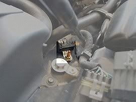
Next is to connect all the wires on the installation kit to the power cord provided by Pioneer. The wire colour match is good. I hooked up the power line to the main ignition switch by tapping into the power wire at that location. I subsequently had problems and eventually ran the power tap down to the spare yellow wire located in the passenger footwell. You could also use fuse #22 if you haven't used it already for something else. The main problem is finding a good earth. Eventually I took earth wires through the bulkhead in the passenger wheel well to the main earth point aft of the headlights. The earthing point (Ground Distribution Cell 14) is on the driver side, seen below . Remove the 10mm bolt and use a crimp-type ring-shaped terminal connector to secure the ground to the bolt. You may also want to solder the end, heat shrink it, and tape it.
The illumination wire can be connected at the hatch release fog light switch. If your car is an automatic, a connection could also be made at the gear indicator lights.
Next, drop the wires into the dash and route the bundles down to the glove box area. It takes some time to feed the wires down. Before installing the head unit you need to set the impedance on the rotary selector on the harness. This is a one off adjustment to personal taste.
The head unit mounts into the car using the GM specific car stereo installation kit. The housing supplied with the N1 fits into the installation kit. You may have to cut out small pieces of the aluminium structure of the dash at the rear of the radio to make the unit fit properly. Its a fiddly install and the screws provided by Pioneer to mount the radio into its housing are tiny! I found I had to make adjustments to allow the radio housing to fit past the bolt heads provided with the installation kit. Once the housing is in the kit, its an easy fit into the dash with a couple of screws. Fit the installation kit first, connect the harness and AV lead and then feed in the head unit being careful to ease the wiring bundle into place and not trap wires. Struggle for a few minutes with the tiny screws being careful not to strip the threads.
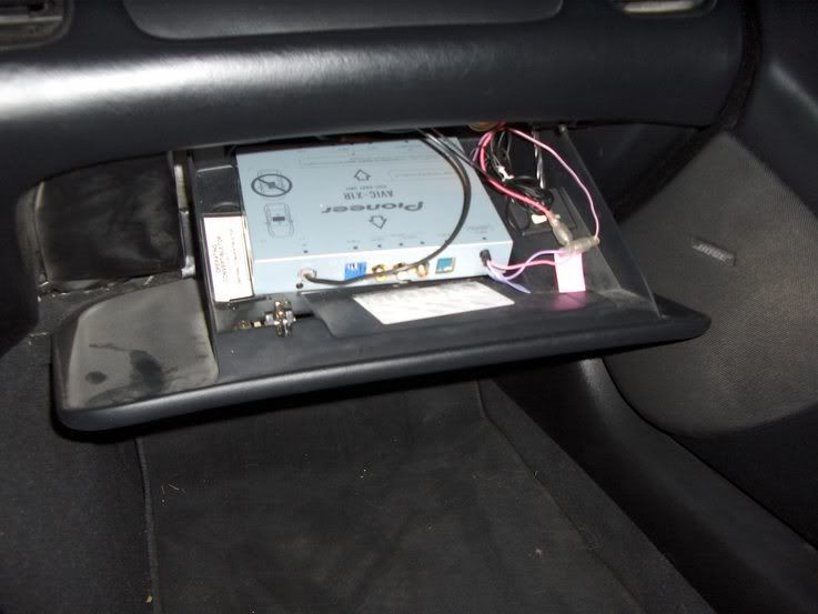
I looked at various alternatives for the hideaway box. It needs to sit flat and the orientation is critical (marked on the unit). It would not fit in the dash space without rearranging the order of the units (radio, A/C unit and ashtray). The preferred location would have been under the passenger seat but the routing for the wires was complex. I opted for the glove box. It takes away glove box space but the owners manual still fits below the unit. The wires feed in easily through a gap at the back of the glove box. Once the wires are all routed correctly, hook them up to the hideaway.
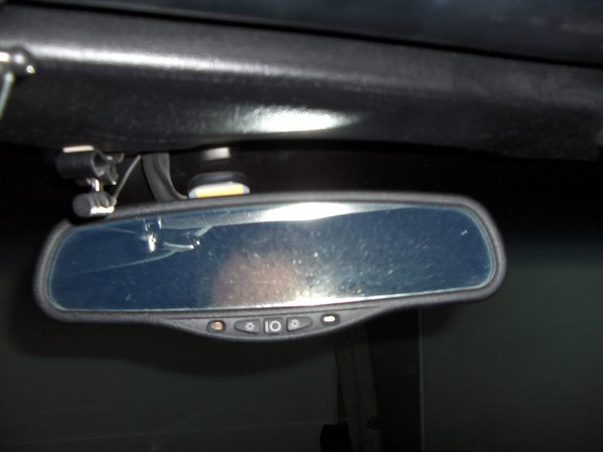
I mounted the GPS antenna on top of the rear view mirror and ran the wires around the top bar of the windscreen. The installation instructions stress that you need the metal plate (supplied by Pioneer) to ensure adequate GPS sensitivity. I didnt use this plate and have had no problems so far. Accuracy seems good without it and the installation is much neater.
I routed the reverse wire around the back of the glove box, up through the door post, along the door sill and up the rear door post, around the convertible top housing and through the rear side wall of the boot behind the carpet. I then drilled a small hole through the bulkhead into the rear bumper area and fed the wire through. To attach to the reversing light circuit you need to remove the number plate housing. The screws are obvious.
The most complex hook up is the VSS wire. The PCM is inside the passenger wheel well and you may need to jack up the car to access it. I managed by turning the wheel fully to the left. The access panel to the PCM needs to be removed. Make sure to remove the three screws underneath the car that are partially hidden from view.
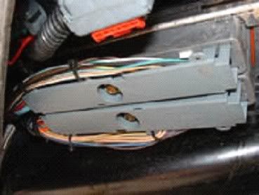
Below is a picture of the PCM. You will have to lie on your back and slide under the car to see this. PCM 2 is closest to you. On the 2000 Corvettes and up PCM, the VSS wire is c2 pin 50 and it is a green/white wire. You can see the pin number by squeezing the end of the grey cover and releasing the clip and moving the cover to the side. I used a crimp type connector to splice into this wire.
I've since heard that you can tap into the VSS wire in the instrument panel area. Worth a search because if you can get to it there and are confident you have the correct wire, the installation will be much easier.
The parking wire should be connected to the power side of the parking brake circuit. To view DVDs on the move (a dumb idea!) or operate the nav kit rerouting function while driving (actually often quite important and straight forward), instead of hooking the wire to the parking brake as instructed, attach it to earth. This will not work on the N2 and N3. However, you can achieve the same effect on the move by clicking the parking brake on a couple of notches. This earths the circuit without bring on the brake. You can then make changes on the move.
Reinstall the console and reconnect the battery.
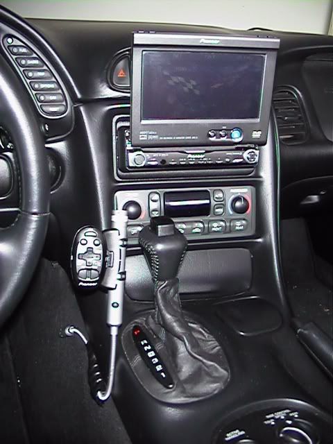
The finished Installation:


 Linear Mode


