Today I took video and pics of everything I could in the rear wheel well so if I forget how something goes together when I'm trying to put the new half shaft back in, I'll have something to reference.
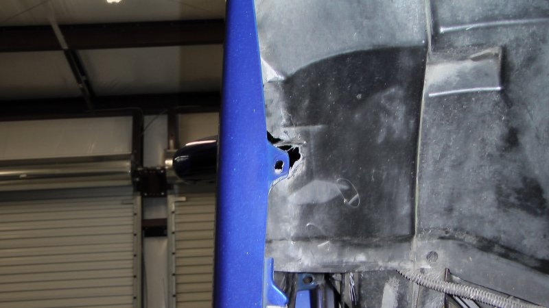
Then I decided to tackle that peek-a-boo air inlet STS pipe that was sticking out of the front of the passenger side rear wheel well. Biggest issue was just getting to the pipe to figure out what was wrong. I had never taken out the inner panels for the wheel wells before, and I had to do that front and back to get to everything. Also needed to loosen up the front fender to get to the couplings up front there. This all went pretty smoothly, but I did find an attachment point for the front fender at top of the wheel well that apparently Aaron ripped out. I know he had been taking the PCM out and putting it back again quite often for Jim while there were working on the tuning, as they were putting the PCM on the bench to do the hookup to their PC. My guess is that Aaron did not remove that top attachment screw and eventually just ripped the darn thing out.
Not sure if there is any way for me to fix that chunk taken out so I can put an insert in there to attach a screw to.

Also found several screws and nuts missing here and there that I need to try to find replacements for. One of the nuts used to hold the brake cooling inlet bezel in front of the rear wheel opening was run out all the way to the end of the attachment screw and not even holding the bezel in place. Since the front one was missing completely (but it's nearly impossible to get to that with the STS pipe in place) there were only two out of four nuts holding it to the body panel.
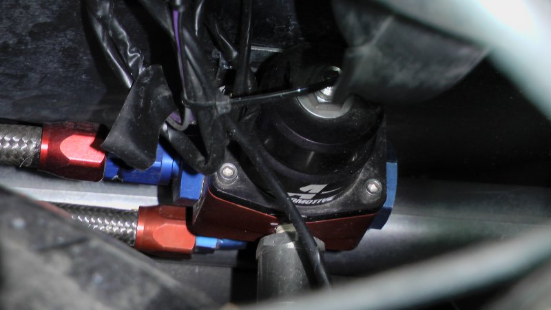
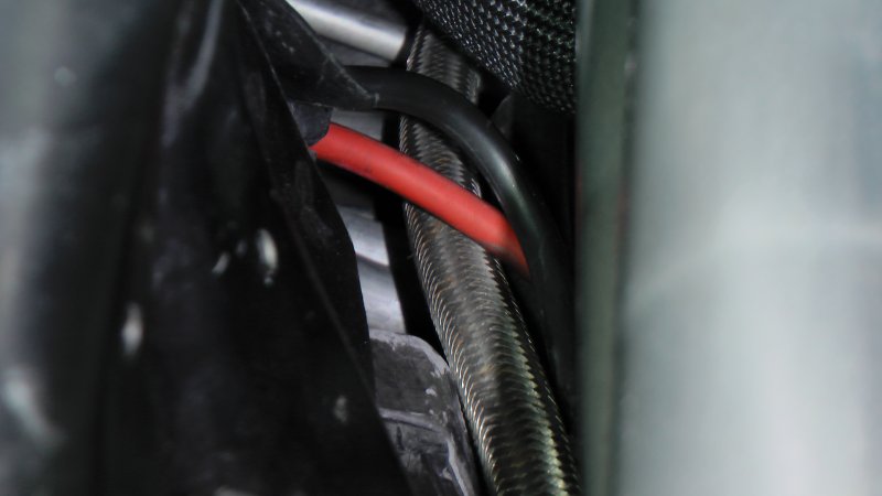
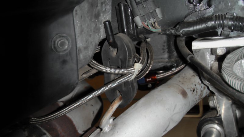
And it certainly is impressive looking at a braided hose that was too long, and instead of shortening it to the correct length, just got wound in a loop around the tail pipe support.....

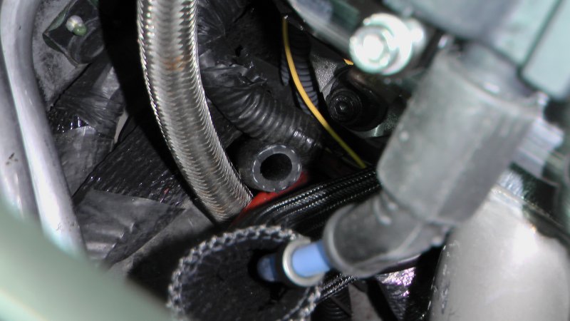
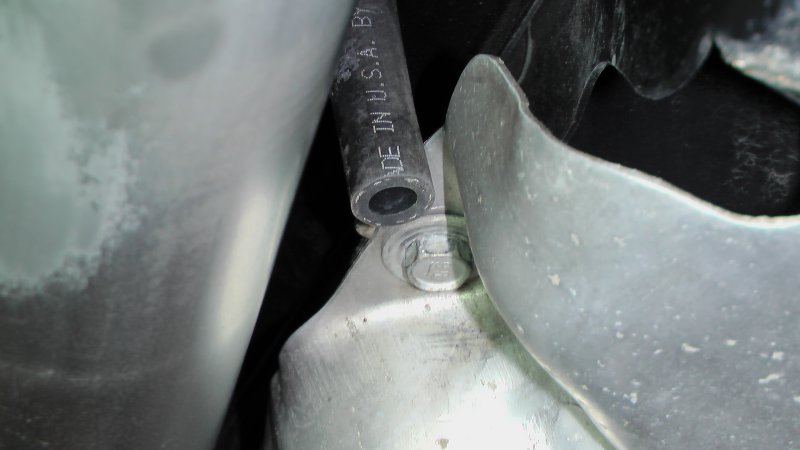
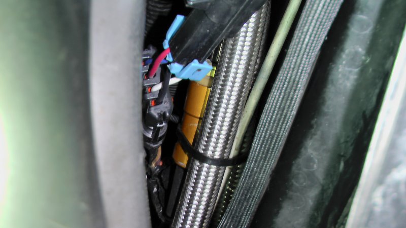
Anyway, the STS pipe was just too far back, so I had to loosen all of the clamps and move the pipe forward till it cleared the wheel opening. This sounds easy enough writing it, but I actually had to use a rubber mallet to coerce the tube forwards. It's jammed in pretty good and even the coupler clamp up front was a challenge to move, as it was pinned against the frame from the pressure of the tube against it. The coupler up there behind the fender panel doesn't look like a regular STS coupler, and seems to be thinner. It appears someone put an additional third hose clamp there, I guess to keep it from bulging in the gap between the two pipe ends under boost. That would be a real pain in the butt to get a thicker coupler in there, so I decided to just leave it and hope for the best. Maybe sometime I'll try to find a WIDE hose clamp to put in there instead of trying to pull that coupler out and replace it.
I had to slit a section of coupler so I could fit it around the top of the pipe going over the wheel well to act as a buffer between the pipe and the frame, and then jammed the pipe in there tight while tightening down all the coupler clamps. Doesn't rattle any longer and I think it looks MUCH better now...
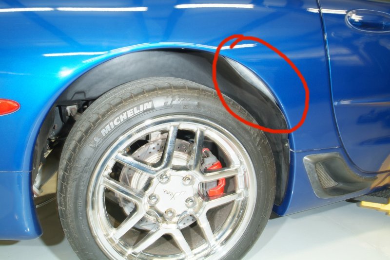
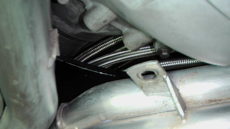
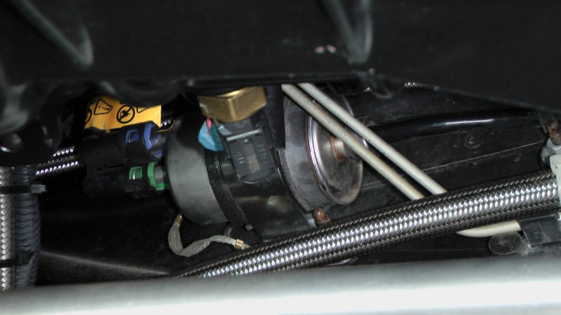
Before:
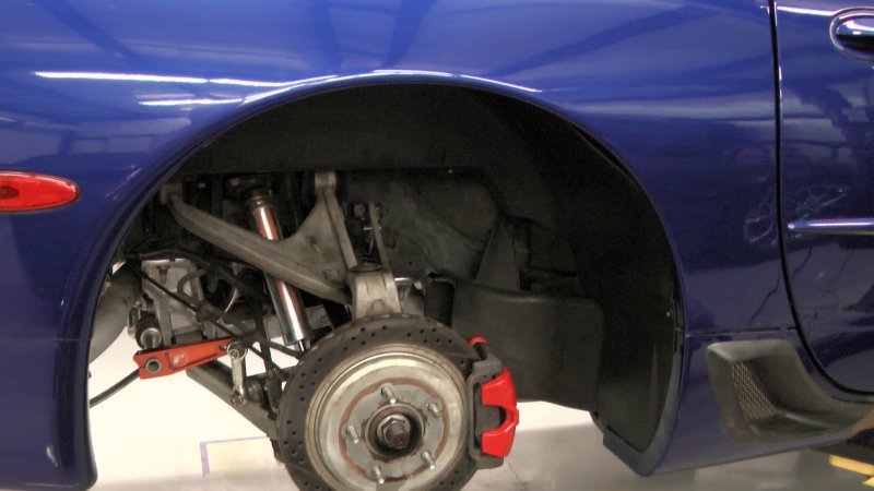
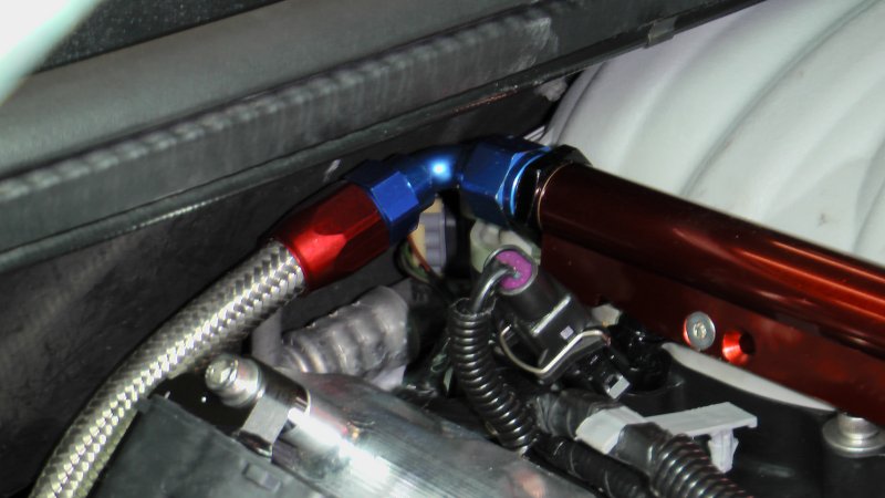
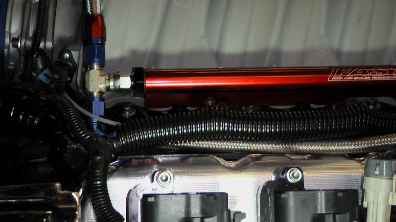
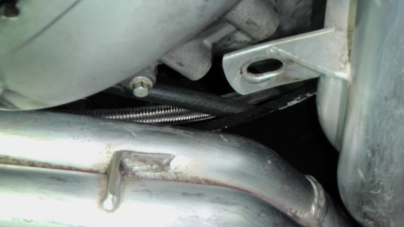
After:
Oh yeah, I checked and I don't have a 34mm socket for that nut on the end of the half shaft holding the hub to it. So I need to get one before those half shafts come in.
At least I felt like I got SOMETHING accomplished today...