• Got the Contributing Memberships stuff finally worked out and made up a thread as a sort of "How-To" to help people figure out how to participate. So if you need help figuring it out, here's the thread you need to take a look at -> http://www.corvetteflorida.com/forums/showthread.php?t=3581 Thank you, everyone! Rich Z.

427 engine (part 2) - RHS block

Wait till you get to the part were you bring the car home. Yes that was a time of discovery and disappointment but as Paul Harvey would say heres the rest of the story. You have been methodically correcting the problems you have found. While doing that you have had many people help with parts and ideas (priceless) If you are any thing like me with each thing corrected you have had a feeling of satisfaction knowing it was now how you wanted it and you did it yourself. Your careful research has been an example to us on how to go about correcting a problem and not just jumping in with both feet. Your patience has been rewareded with success after success with your own hands. You have had the support of your wife even to her being able to give you an extra hand when you needed it (I envey you that). I believe the good will outway the bad in the end. You have said you wanted this to be a show piece car at events and meets and it will but it will also be a reflection on you and the dream you had for this car. I am waiting for the last chapter were the maiden gets the prince and they happily ride off into the sunset.
 
Well, I guess that if I get to the point where I feel that I could confidently drive this car all the way across the country to California, like Aaron claimed he could when I picked up the car, and not worry about it breaking down on me, then I will be satisfied that it is truly fixed. But I think that is a long way away from realization at this point.

Honestly, if I could afford it, I would just rip out everything touched by Chris Harwood and Aaron Scott, send the engine back to LME to have it thoroughly checked out, and then start over from scratch. Had I known when I started this project what I know now, I would have just bitten the bullet and done all this myself. Just bought the tools and equipment necessary, find the help and expertise to guide me all along the way as needed, and just done every bit of this myself. Yeah, I would have made some mistakes, but I wouldn't have lied to myself about them and tried to blame them on someone else. If you make a mistake, just man up to it and FIX it. Even not knowing what the hell I was doing, I'm certain it would have been done a LOT quicker and it certainly would have been running by now without all the issues I have found that were done wrong, done in a slipshod manner, or just not done at all, contrary to what I was told. Even with the absolutely worst case scenarios taking place doing it myself, it certainly couldn't have been any worse than what has already taken place to date. And it certainly wouldn't have completely ruined the first couple of years of retirement for Connie and myself.

Yeah, I did learn a lot from all this. And not just about the car.
 
And btw, it's just not this saga of my own car that I found so painful reading over the past displayed in this thread. It was posts made by Gannet and Mike concerning their cars when they were all excited about getting their cars finished and being able to enjoy them again that I found so discouraging. Last I heard from Gannet (Dave) he was getting rid of his car. Mike is still having problems. Perhaps we all just made very poor choices along the way. But it is depressing as hell to me and has completely put a huge damper on this whole Corvette thing for me and others.
 
I understand where you're coming from Rich. We both made some bad choices on the people we had work our Vettes. If I can't get my car to run without going into reduced engine power after all the parts I've replaced including a TAC Module I may just end up getting rid of mine. When you can't trust the car to drive any long distances what's the point of having it.
 
Yeah, I know Mike. And I haven't even gotten mine to the point where I can start wringing out any lurking gremlins that will likely bite me on the ass as I begin driving the car. To say I am merely apprehensive about this is being a vast understatement. I mean, what are the chances that once I get this mechanical stuff done, and the tuning finished, that I will then be home free with this? :nonod: I feel like I still have the insult waiting to be added to the injury I've been going through.

There will have to be a time when I just have to say that enough is enough.
 
While waiting for the stuff I ordered to show up, I've been doing some cleanup of the back end of the car.

exhaust_cleanup_01.jpg


exhaust_cleanup_02.jpg


exhaust_cleanup_03.jpg


Yesterday Connie and I were poking around underneath of the car trying to figure out a good place to mount that vacuum manifold block. Was a bit perturbed by a rather large rubber hose coming out from underneath the driver side headlight area, so I took off the cover panel to see where that went. It was attached to some contraption there, and there was yet another hose attached to it with a loose end just laying up in the fender. Since it apparently wasn't doing anything, I just removed it and the hoses. Had an electrical connector and what looked like a small vacuum hose going to it, so I capped off the vacuum fitting on the hose and just tied up the electrical connector. Hopefully this isn't something that will cause the PCM to go bonkers when I start up the car again. I'm guessing it has something to do with the EGR system, but all of that stuff has been disabled in the tune anyway. Guess we'll see.

Anyway, didn't look like anyplace convenient to mount the vacuum block in there anyway so we had to look elsewhere. Connie pointed out an area that looked promising that is not far from the fuel pressure regulator. Apparently made out of plastic, but seemed quite strong and rigid... Right inside the rear of the driver side fender.

v_manifold_01.jpg


And it looked like I could get a drill in there, which wasn't the case in some spots we scoped out. So I figured that would be the spot to try.

So today I decided to mount that vacuum block, and it seemed to go remarkably well.


v_manifold_02.jpg


Of course, I haven't tried hooking up the vacuum lines yet to see if there is some problem doing that, that isn't apparent right now.

Oh yeah, the fuel pump came in today from Lonnie's Performance. Looks very well done, from my novice opinion. But the wiring harnesses do look a bit intimidating to me. Not much in the way of directions, but some of the harness ends are labelled and I guess I need to figure it out. But certainly not going to be just an easy case of putting the pump back into the gas tank and just hooking up a single cable connector.

Frankenvette is going to be getting some more new parts put into it...
 
Here's a couple of pics of the fuel pump and the wiring harnesss I got from Lonnie's Performance:

lpa_01.jpg


lpa_02.jpg


I might be working on this tomorrow, I suppose....
 
Got the fuel pump into the gas tank today. For a minute there, I didn't think it was going to go. The bracket holding the two pumps in place in the assembly was a REAL tight squeeze through that opening. Sure as heck hope I don't have to pull that sucker back out anytime.

Going to take a bit to get the wiring harnesses put in. It's not quite as "plug and play" as I had hoped. Kind of like when your doctor says you will have "minor discomfort" after your surgery. ;) But it will get done. The wrinkles are going to be finding how to mount the two relays in the back near the fuel tank, and then running that harness through the tunnel plate area up to the battery. There I have to mount two fuse fixtures. Then from there a two wire harness has to run over to the vacuum manifold block to tie into the Hobbs switch. So this will have to go over the drivetrain and behind the intake manifold. Supposedly that Hobbs switch is set to go on between 3 and 5 psi of boost, but I would like it to come on a little sooner than that. There is supposed to be a way to adjust that thing, but darn if I can see any way to make an adjustment.

Anyway, I took some pics, so I'll post them up later on so you can see what I am talking about.

Still haven't heard a word from the guy I am getting the throttle body from, so I'm beginning to get a bit concerned. It should have shipped by now. I'm waiting on that before I put together the engine side of the fuel system.
 
I laid out the two cable harnesses underneath the car to get an idea of what I have to do to get them hooked up. Doesn't look too tough, but I've come to expect snags all along the way I guess.

Here's the overall harness layout in approximate location to where it needs to go on the car.

harness_01.jpg


Starting at the fuel pump, there are three loose cables now shown there. The one on the right hand side pointing upwards is the original stock cable connector. That one goes to the connector not shown in the pic at the end of the cable that is going off the bottom of the picture with the purple wire showing.

harness_a1.jpg


The cable labelled "A" is where the cable harness on the floor connects to on the connector there also marked "A".

harness_a2.jpg


From there the harness runs to two inline relays as well as a ground strap (B).
Each of the new pumps has it's own relay to activate it.

harness_b.jpg


Now after the LONG stretch of cable going up to the front and needs to wind up at the battery, there are three sections of note. (C) connects directly to the battery + and - terminals, and I assume the stock battery cables then screw into those connectors. (D) are a pair of fuse blocks, one for each pump. And (E) which is a pair of connectors, again, one for each pump. Right now they both have a loop wire connected to them, which means both pumps will be running when power is applied.

harness_c_d_e.jpg


Either connector at (E) can then be connected to the other harness end (F) which goes to the Hobbs switch located on the vacuum manifold block. The connetor at E selected for this harness will then become the secondary pump that will only be activated when the Hobbs switch detects boost at somewhere between 3 and 5 psi. Also note that the connector can be switched at (E) to alternately run each pump as the main pump and thereby try to equal out the run time on each pump.

harness_f.jpg


And of course this is the other end of the second harness that attaches to the Hobbs switch itself. This switch will be screwed into the vacuum manifold block I just installed recently behind the driver's side fender.

harness_g.jpg


Doesn't look too tough to hook up, but I think mounting those relays near the fuel tank is going to give me some issues. Just no way to get a drill up in there to drill mounting holes while the drivetrain is installed, so I'm going to have to try to use any existing mounting points that I can. I guess I'll have to pull out the battery in order to mount the fuse blocks and those loop connectors onto the firewall where they will be somewhat accessible. I'm planning on replacing the battery anyway, as it's apparently taken a beating before the car came back home. I'll probably get a yellow top this time around, as I believe it is better for higher than stock current draws while the car is running.

So that's what I have to look forward to in the next few days.
 
Now after the LONG stretch of cable going up to the front and needs to wind up at the battery, there are three sections of note. (C) connects directly to the battery + and - terminals, and I assume the stock battery cables then screw into those connectors.

harness_c_d_e.jpg

I'm pretty sure you can take out the terminal ends on your stock cables, and these should slide/snap into place. Just had to do the cables on my 96 as i ran a 0 gauge from the alt directly to the battery and a 0 gauge from the battery to the frame. They basically pop in and out...but with a lot of cussing. Not sure if these are suppose to do that, but it looks like it from the pics. The screws on the back are for those with additional power needs like stereo amps and such.
 
Actually, I would like to put top post mounting ends on this harness and just hook it up to those unused posts on the battery.
 
After further review, these certainly replace your stock end terminals. They are the exact ones I have. But yeah, you can pick up the top mount terminals at your local auto parts store or stereo shop. I would recommend getting the gold plated ones like they've used.

I'd get the ones like this.
http://www.autozone.com/autozone/accessories/Tsunami-2-4-and-2-8-AWG-holes-24K-gold-plated-negative-battery-block-terminal/_/N-25hn?itemIdentifier=388120_0_0_

Yeah, I've looked at those, but I don't see where they will allow me to directly thread the bolt from a side mount connection to them. They look like they are set up to crimp in 4 and 8 gauge wire. Or am I just looking at them wrong?

So far the only thing I've found that comes close to what I THINK I need is this -> http://www.amazon.com/gp/product/B000BQYGR6/ref=ox_sc_act_title_1?ie=UTF8&m=AATF6ZARMZ4LJ
 
Didn't think about keeping the ring ends. I'd cut them off and insert them into the top mount inserts, but then you have an altered harness. This is how much truck is ran for all my audio equipment. The one you posted would work, you may have to find bolts if the gold plated ones don't fit...which should be easy. I'd still just swap out the stock side posts. They really aren't that hard to replace.
 
At this point the easiest method that doesn't compromise the quality is what I am after. I'm going to go ahead and order those adapters I indicated and see what I've got when I get them here. One way or another I'll get the harness to work with something. I've got a 25 percent off coupon from AdvanceAuto, so that Optima Yellow Top battery I want won't cost me as much as paying normal prices. The Red Top batteries I've had in the car just haven't lasted as long as I would have hoped for.

Thanks for the suggestions. I'm feeling more comfortable about wrenching on this car, but it's still kind of intimidating with all the electronics doohickeys than can go wrong. It makes my heart skip a beat just seeing the battery cable connectors throw a spark whenever I connect or disconnect them thinking that the impulse created will zap something in the electronics.
 
Well at least you aren't colorblind. Trying doing electronics work when you can't tell the green wire with white stripe from the brown wire with white stripe! If it's beyond black and red, I have to send it out, which blows.

I tried to hook up a keyless entry for my wife's car...let's just say that didn't go as planned. Sad thing is, I knew better.

Ouch.... Yeah, I can see where that would be a definite handicap doing this sort of thing. Looking at a harness and reading instructions saying something like "Locate and cut the BROWN wire" would definitely be a problem.
 
Well today (actually Thursday) went pretty well. Seemed like I got a lot done, but as I am sitting here thinking of it, no, there really wasn't THAT much done. But it sure seemed like I was working like a lot was getting done.

Put the Hobbs switch onto the vacuum manifold block and also put in the two vacuum fittings I expect to be using and plugged the other remaining three holes. Then ran the cable harness from the Hobbs switch to the battery compartment over on the passenger side where the main harness was going to be located.

hobbs_01.jpg


hobbs_02.jpg


I then removed the battery so it wouldn't be in my way during the rest of this procedure. Maybe while it is out I need to take a look at the relay sitting behind it that is supposed to work the STS oil scavenge pump. I really don't like that it runs constantly when the ignition switch is on like the fuel pump used to, so maybe the STS manual will tell me how it is SUPPOSED to be hooked up. I'm thinking I may need to merely find the signal line that is supposed to activate the relay and just move a couple of wires to fix this. Hopefully the signal wire wasn't cut.

Anyway, running the harness through the tunnel valley over top of the tunnel plate wasn't as easy as I had hoped. I seriously thought several times I was going to have to pull off the exhaust and take down the tunnel plate in order to do this. I cut down a thin length of bamboo and really had a devil of a time feeding just that through the tunnel plate area. In hindsight, I think it just was not flexible enough and was coming through too high in the tunnel valley hitting against wire ties holding the fuel and oil lines laid up in there. Connie was helping me with this, btw, and we finally were able to get the length of bamboo completely through. I taped up the connectors on the end going to the battery compartment as best I could, trying to make it as compact as humanly possible, but it still looked huge to me. I was thinking that if I had trouble getting just that length of bamboo through there (which was only 1/2 inch in diameter) there was just no way in hell that big darn bundle was going to go through there. But I taped the end of that bamboo shoot to the end of that harness and started pulling from the front end, really not at all confident that this was going to work. Surprisingly enough, the harness end did come all the way through the tunnel and just as I saw the end of the harness peek through, the bamboo shoot pulled loose from it. But I was able to grab it by hand and pull it the rest of the way through. Whew!! Man, I REALLY didn't want to have to pull off the exhaust and that darn tunnel plate!

harness_10.jpg


After that I then had to feed that harness end up past the header on the passenger side and the starter and then guide it into the battery compartment. Not all that easy, and honestly the entire time I was thinking "Plug and play my ass!". :lmao:

But it's in there now, so I think the hard part is now over with. I've got to mount those fuse blocks onto the firewall and figure out how to put those loop connectors someplace where I can get to them relatively easily to switch the primary and secondary pump every so often. And of course I am waiting on the battery terminal adapters to hook up the power to the harness. But that shouldn't be any real big deal to do.

harness_11.jpg


I guess I'll tackle the rest of that tomorrow, and maybe work on the rear end of the harness to see about mounting those relays and that ground strap. Looks like I have a lot of extra cable harness, so I'll have to figure out where to bundle that up and have it out of the way and not close to any heat sources or moving parts.

Oh, speaking of heat sources, I went and covered the harnesses that were running over top of the headers with that Taylor's brand convoluted tubing as it is supposed to withstand temps of up to 1,000 degrees. Kind of gaudy looking, being chrome colored, but what the heck. If it does the job, then I'm OK with that. Besides, I've been using it to cover most of the wiring and vacuum tubing around the engine anyway, so what's a little bit more?

http://www.summitracing.com/parts/TAY-39000/

So yeah, this seemed like a GOOD day today. If I think about the fact that I didn't have to pay someone $50 to $100 an hour to do this stuff, then it was a REAL GOOD DAY. :thumbsup:
 
Didn't really do much today. Connie and I had to run up into Tallahassee to do some errands, and I didn't feel like drilling into the car and trying to mount relays and fuse holders.

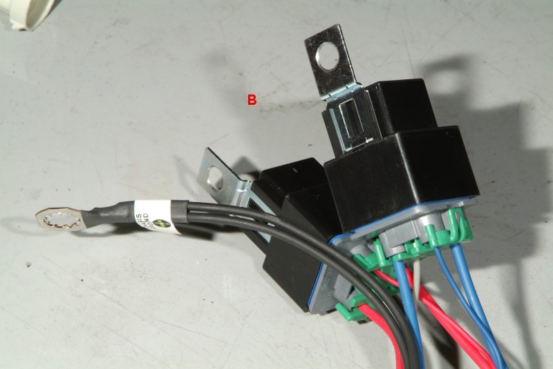
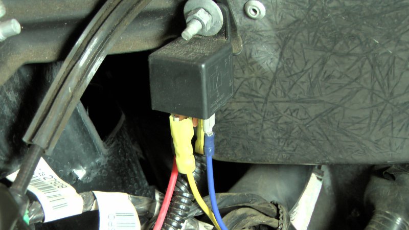
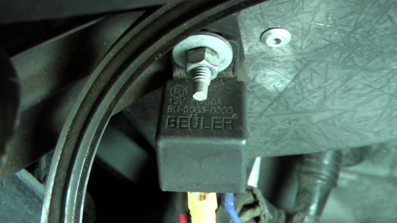
So I decided to take a look at the wiring for the STS oil scavenge pump to see if I could figure that out and get it back to the way it should be. Meaning that I want it to run much like the fuel pump and ONLY be on when the engine is running. So I decided to start where I think the problem has to be at. The relay.

sts_relay_01.jpg


sts_relay_02.jpg


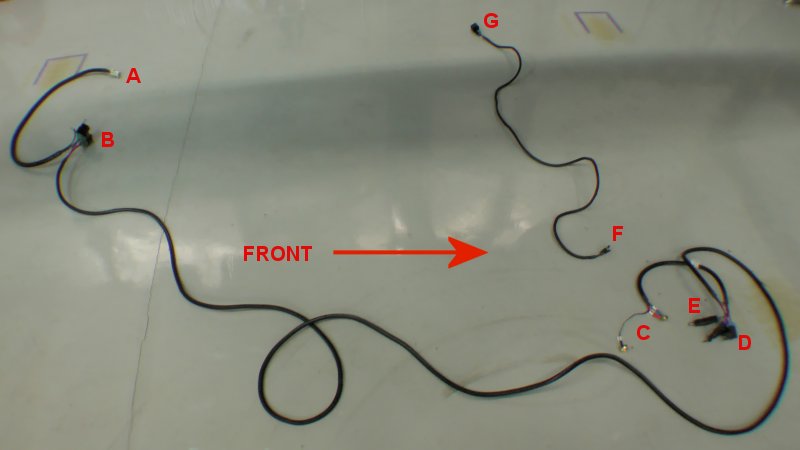
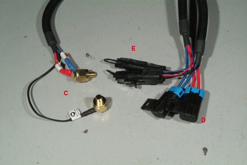
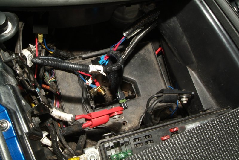
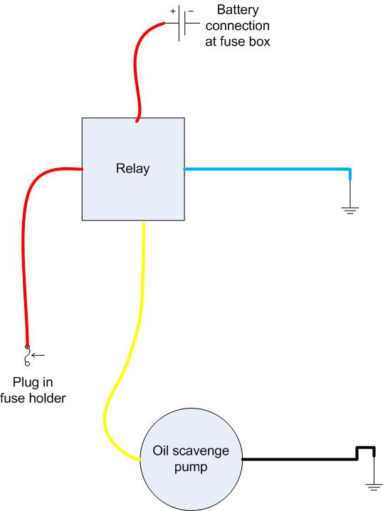
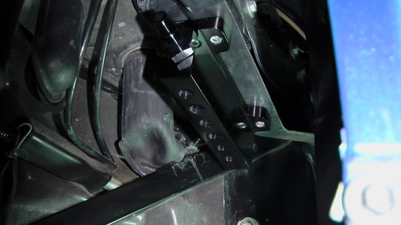
I traced the wires and here's what I came up with.

  • The RED WIRE runs to the top of the fuse block and plugs into a fuse socket. This is the wire I would pull when I wanted to shut off the scavenge pump when I needed the ignition switch to be on.
  • The wire with the convoluted tubing on it is also a RED WIRE and that one goes to the + side battery connection that provides power directly to the fuse block itself. This has an inline 15 amp fuse on it.
  • The BLUE WIRE runs to frame ground.
  • The YELLOW WIRE runs to the + terminal of the oil scavenge pump.

sts_relay_03.jpg


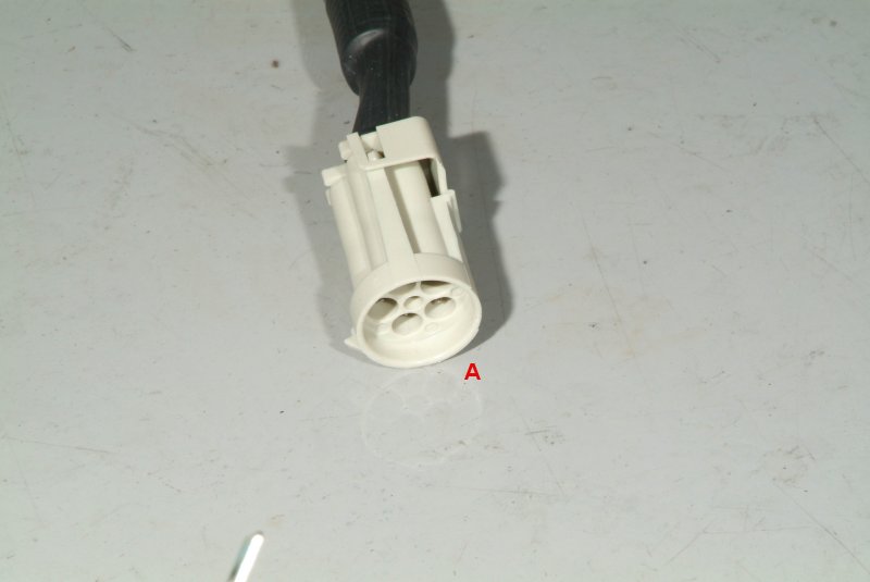
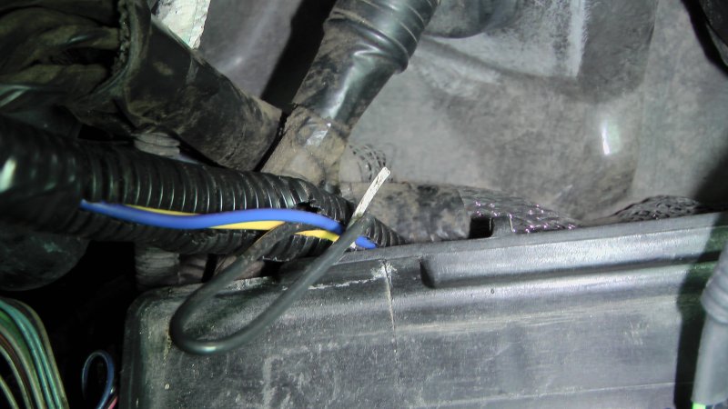
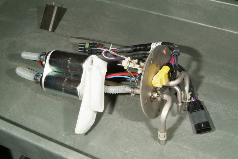
I opened up the wiring harness that the yellow and blue wire run into, and found a white wire and black wire that had been cut off there. As best I can tell, these cut wires go to the oil pressure switch at the scavenge pump and I believe were originally hooked to an alarm to alert when something went wrong with the scavenge pump and no oil pressure detected coming back from the turbos.

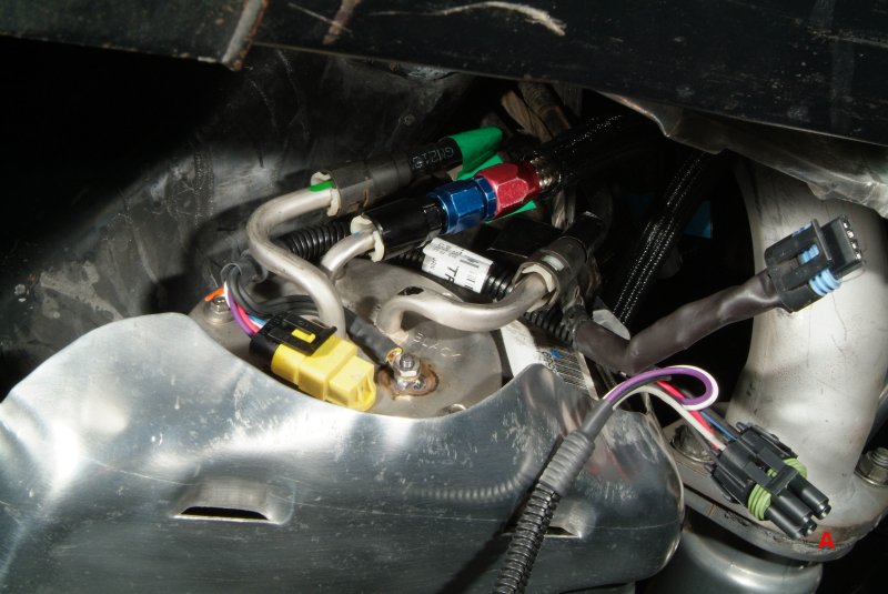
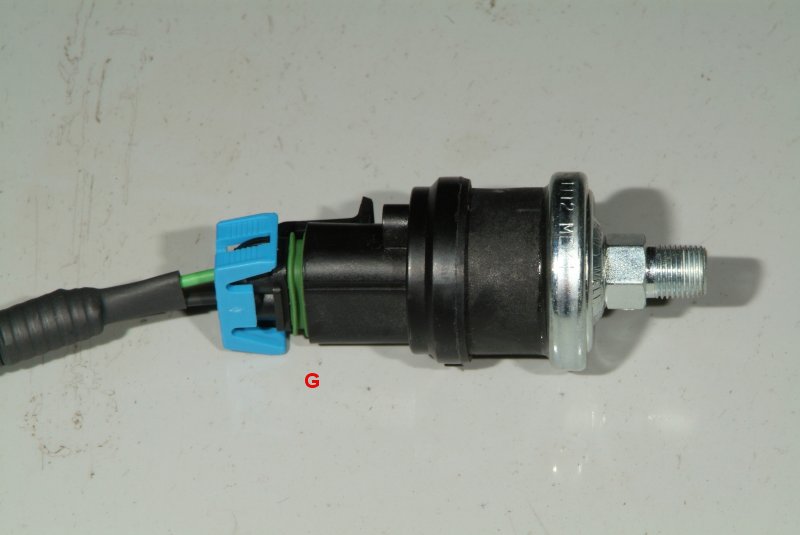
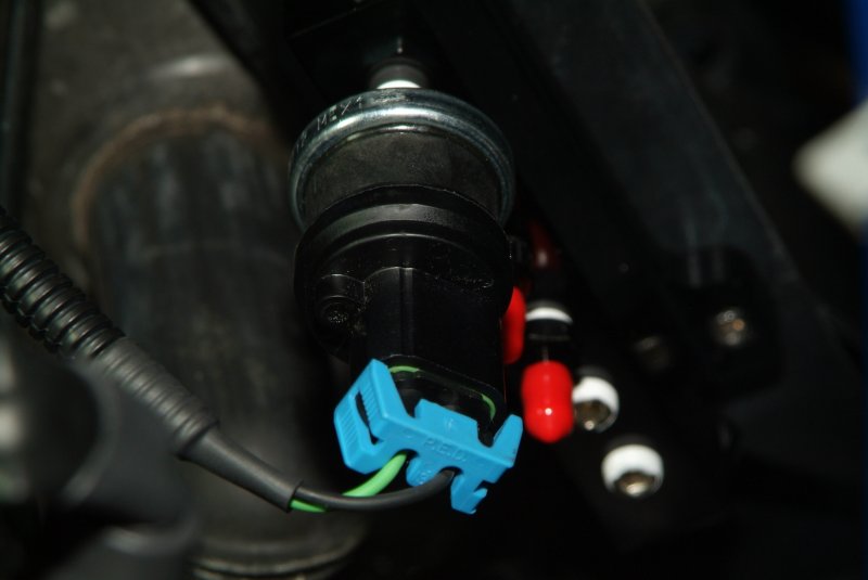
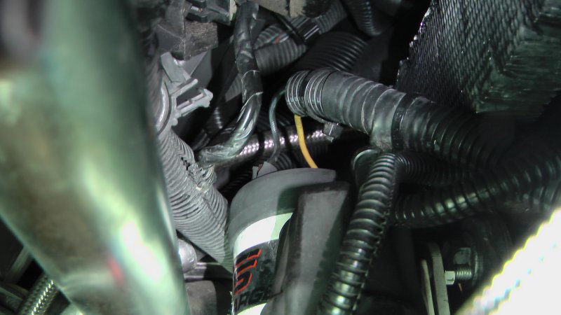
Here's the yellow and black wire at the top of the scavenge pump.

sts_relay_04.jpg


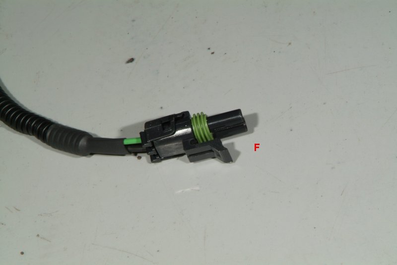
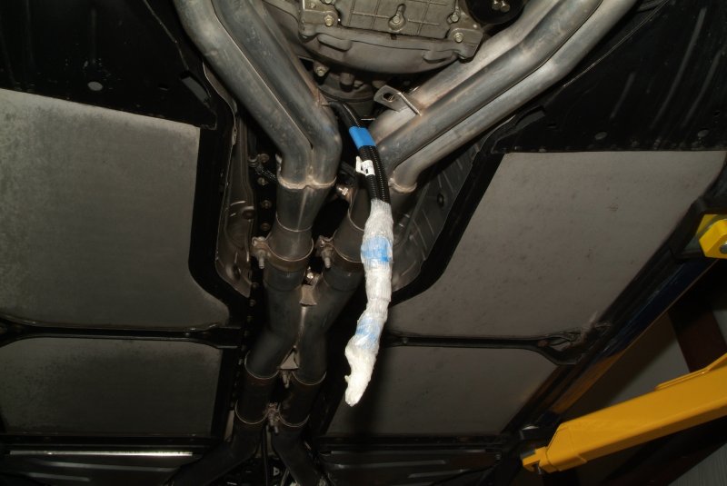
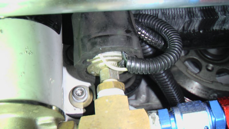
And here are the white and black wires running to the oil pressure sensor.

sts_relay_05.jpg


I think what is going on is that the red wire running to the top of the fuse block is the problem. It is providing constant power to the relay when the ignition switch is turned on. The STS manual mentions something about tapping into one of the power wires running to the fuel injectors, as apparently they operate like the power line running to the fuel pump. When the ignition is turned on and the engine isn't started, power shuts down to the injectors after 2 seconds. So I think all I need to do is to tap into one of those injector power wires and run that wire over to the relay to replace that red wire.

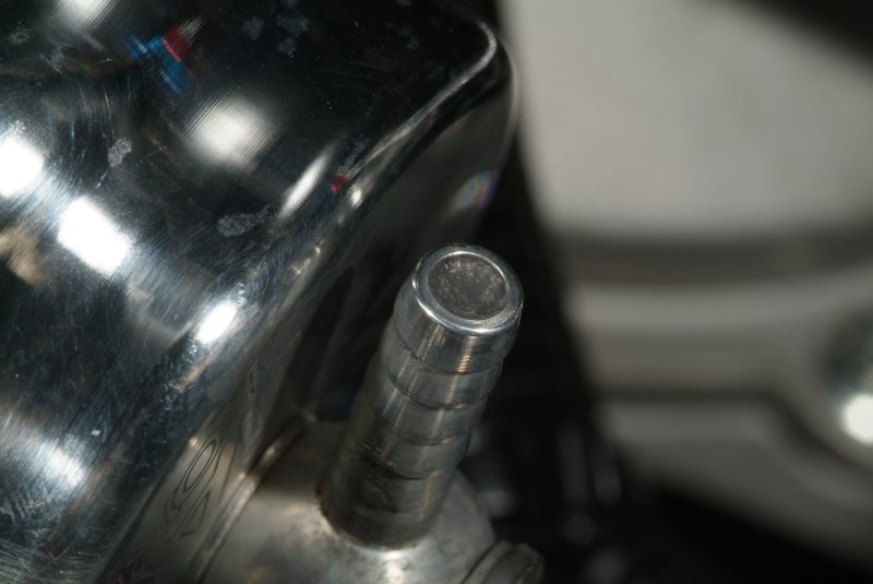
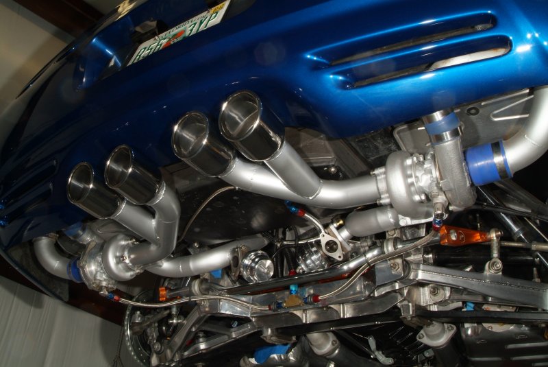
Anyway, when I cracked open the STS manual, the first pic I see is of one of the turbo wastegates. There is a bolded notice there stating
The Rear Vent Port on the wastegate must be vented to atmosphere.

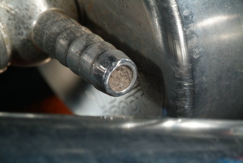
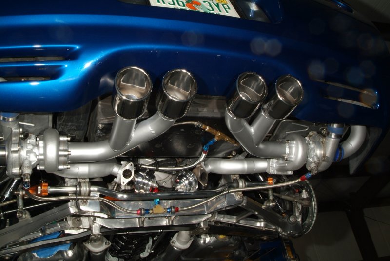
Hmm, seemed to me that I recall looking at the wastegates on my car and they didn't appear to have those ports open. So I went over and checked them out.

Double hmmm.....

wastegate_dside.jpg


wastegate_pside.jpg


The manual doesn't really say anything about what would happen if they are NOT vented to atmosphere, but it does say that applying boost pressure to that Rear Vent Port and/or not applying boost pressure to the Front Boost Port will cause the wastegate to stay closed and the turbo to over-boost.
This will cause IMMEDIATE SEVERE damage to the vehicle's engine!

Sheesh.... Great....

I sent STS an email to get their take on this situation. Might be a darn good thing I didn't get heavy with the GO pedal driving the car home back in November.

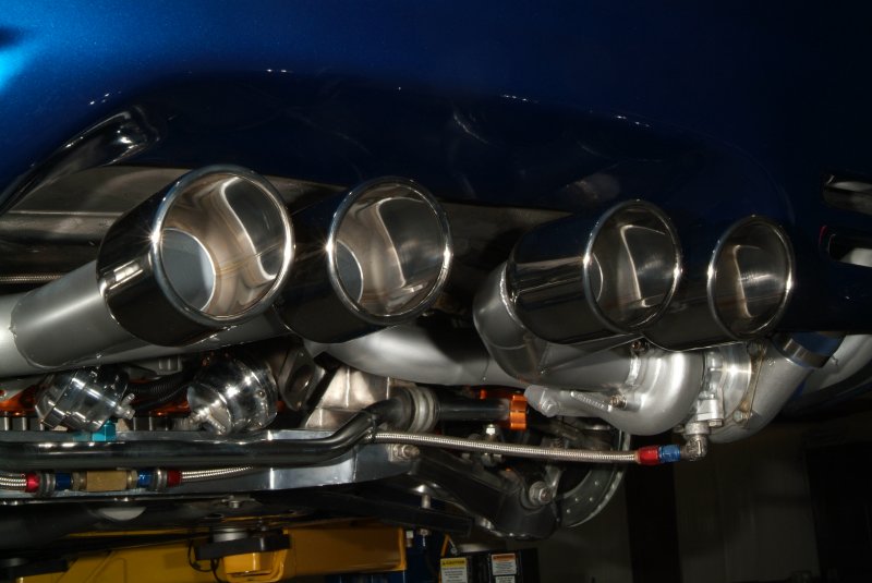
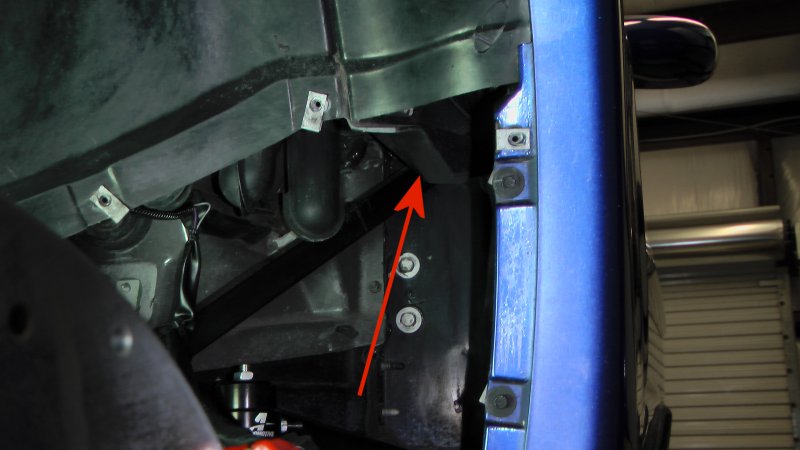
I did trace the vacuum lines from the Front Boost Port of both wastegates and they do appear to be connected to a vacuum port on the back of the intake manifold. I had to use a flexible inspection camera in order to check that out. Oh yeah, I got to see that MAP sensor back there too...

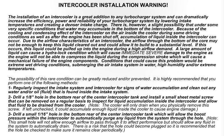
So I was leafing through the STS manual while eating dinner, and this notice caught my eye.

intercooler_warning.jpg


Unfortunately it doesn't tell me HOW to inspect the intercooler. Why would this concern me? Well, I was told by Aaron three times while he had my car that the air intake piping had inadvertently been exposed to oil because of one reason or another. So he cleaned the oil out by somehow washing out the plumbing each time. That is three times that I am aware of that fluids have been in the intake, meaning quite likely into the intercooler, of the STS system.

I would hope that the intercooler was flushed and dried out properly each time, or at the very least any water or cleaning fluid in there would have evaporated over the last few months, but heck, do I really want to take that chance? Suppose there is still oil in that intercooler? I know when I was cleaning up underneath the car recently that there were signs of oil having come out of the blow off valve attached to the bottom of the intercooler.

So yeah, looking through the STS manual has just been chock full of fun today...
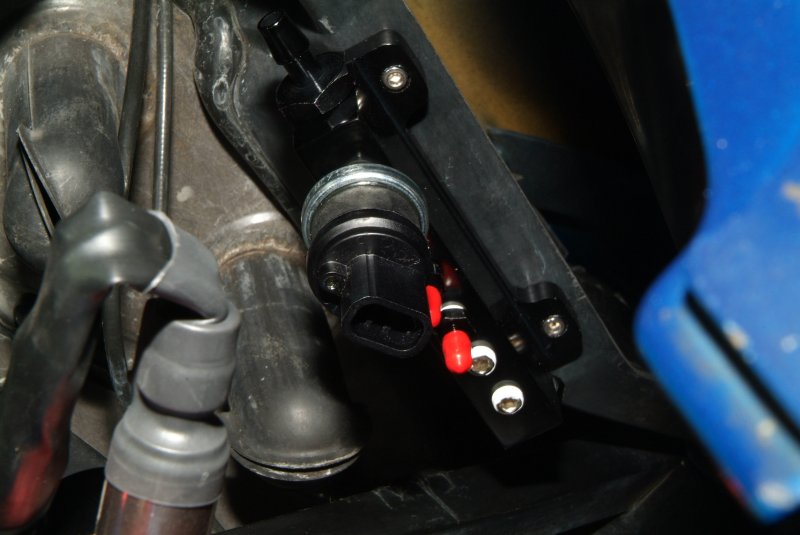
 
I traced the wires coming from the relay for the STS oil scavenge pump, and here's what I came up with.

scavenge pump relay 01.jpg


The STS manual calls for a wire to be spliced from the #2 cylinder fuel injector wire to activate the relay, but I don't see any evidence of a splice there. Ed Hutchings recommended splicing into the gray wire running from the fuse box to the fuel pump, and after thinking about it a bit, I think that may be where Greg originally spliced the wire when he installed the STS system for me. So I'm going to poke around and see if I can locate that gray wire, and hopefully find a spliced wire already attached to it. In any event, I believe the spliced wire would need to replace the red wire running from the relay to the fuse holder on top of the fuse box to make the scavenger pump work like it should.
 
Back
Top