• Got the Contributing Memberships stuff finally worked out and made up a thread as a sort of "How-To" to help people figure out how to participate. So if you need help figuring it out, here's the thread you need to take a look at -> http://www.corvetteflorida.com/forums/showthread.php?t=3581 Thank you, everyone! Rich Z.

427 engine (part 2) - RHS block

Rich, would the abrupt change (throttle plate open to closed like during a shift)
be a likely cause of the separation of the plumbing at the air bridge/coupler/
throttle body area that you've been seeing? That area might be ok for low
delta changes, but when smacked all of a sudden, it lets go.......
Just wondering (in print, NOT out loud! LOL)
Andy :wavey:
Sounds like you're creeping up on it slowly but surely, which is DEFINITELY
the preferred way to go! :thumbsup:

Possibly, but I just don't know. I originally thought that the hiccup that happened the first time was caused by the airbridge coupler separating under pressure, but after I fixed that the hiccup happened again and the airbridge coupler was still intact afterwards. So it's quite likely the hiccup had nothing at all to do with the separation and was just a coincidence of sorts. The logs don't show any spike in the pressure, but that would make sense in that the logs are pulling vacuum/boost info from the intake manifold via the MAP sensor, so anything happening on the outside of the throttle body plate would not show up in the logs.

So honestly, thinking about everything that could be affected by that rapid transition from boost to vacuum, I think the device most affected might actually be the fuel pressure regulator. I'll have to look at the logs again, but I would think there would be a sharp peak of fuel taking place during the period when the throttle body blade snaps shut and before the FPR can react to that sharp transition from providing more fuel for boost to what the PCM really wants when the engine is running under normal conditions with vacuum in the plenum. Probably not really significant, though, since I don't think this can all ever really be perfect under all conditions thrown at an engine.

I guess the biggest question I've got now that I'm trying to solve is WHY am I not getting more than 7 to 8 lbs of boost off of 10 lb wastegate springs? With the wastegates being referenced at the plenum (intake manifold) there really shouldn't be any losses to account for. My guess is that perhaps at least one of the springs really is not a 10 lb spring at all, as all it takes is for one spring out of the two to be weak or under spec and that will be the one that actually controls overall boost to the engine. The X pipe in the exhaust does not allow both sides to be completely independent as it tends to equalize the pressure all throughout the exhaust system. I guess I can test the springs when I pull the wastegates off just to see if one opens earlier than the other under pressure.
 
you can make a fitting and hose setup using a small adjustable regulator and a gauge and use shop air to activate the wastegates. get the shop air, connect the regulator to it, then a gauge between it and the wastegate. then adjust the air pressure until you see the wastegate start to activate (note the PSI) and then when it is opened up all the way (note the PSI). then check the other one. they should be the same. if they are different or under spec then that is your problem. if they are both dead on 10psi and the same as each other in the opening and wide open pressures, then I believe that the issue is exhaust back pressure related. that can be compensated by increasing the wastegate spring "weight" like you plan to with the 14# springs.
 
you can make a fitting and hose setup using a small adjustable regulator and a gauge and use shop air to activate the wastegates. get the shop air, connect the regulator to it, then a gauge between it and the wastegate. then adjust the air pressure until you see the wastegate start to activate (note the PSI) and then when it is opened up all the way (note the PSI). then check the other one. they should be the same. if they are different or under spec then that is your problem. if they are both dead on 10psi and the same as each other in the opening and wide open pressures, then I believe that the issue is exhaust back pressure related. that can be compensated by increasing the wastegate spring "weight" like you plan to with the 14# springs.

Yes, I believe you mentioned that to me before that the exhaust also exerts pressure on the valve of the wastegates as well as the pressure coming into the body of the wastegates to activate the valve. Which makes sense to me. Action versus reaction and that sort of thing. So the springs themselves are being acted against by two different forces. Boost is being produced by air being compressed at the compressor side of a turbo, that pushes against the diaphragm, and obviously some sort of pressure is exerting force on the turbine half of the turbo via the actual exhaust gases directly upon the face of the wastegate valve. The spring held valve of a wastegate is affected by both forces, but I'm not sure how much one force influences it over the other.

So is this a 1:1 ratio of force, or is the force being multiplied at the compressor wheel at a different ratio? In other words, does 1 pound of exhaust pressure produce 1 pound of boost? If not, then what ratio is being used? I'm guessing that there must be a pertinent ratio difference based on the size of the blades for both the turbine and the compressor side, which may be what those "A/R" numbers represent. But what does a turbine of ".48" and a compressor of ".60" actually mean?

I've been trying to find answers as to a rule of thumb about exactly how much back pressure is in the exhaust pipes related to what the turbos are putting out at the compressor site, with no luck. But I'm sure that sort of info must be out there somewhere.

Well, the parts are supposed to be showing up tomorrow. Depends on how ambitious I feel as to when I start pulling the old wastegates out and the turbos apart.
 
So is this a 1:1 ratio of force, or is the force being multiplied at the compressor wheel at a different ratio? In other words, does 1 pound of exhaust pressure produce 1 pound of boost? If not, then what ratio is being used? I'm guessing that there must be a pertinent ratio difference based on the size of the blades for both the turbine and the compressor side, which may be what those "A/R" numbers represent. But what does a turbine of ".48" and a compressor of ".60" actually mean?

"Theoretically" a 1:1 ratio is ZEN on a turbo setup, meaning it is optimal and is most efficient at a 1:1 ratio, meaning 10psi of boost for every 10psi of exhaust back pressure. Think of the engine as a simple air pump, which it is, as it can only put out what comes into it. but when the exhaust housing is small, it creates backpressure and will make the ratio creep upwards of a 1:2 ratio. Right now it looks like you have a ratio of 8:10, 8psi intake to 10psi exhaust. or 1:1.25 ratio

While a small exhaust housing is optimal for spoolup, and is commonly used in rear mount turbo systems to help reduce turbo lag due to them being a rear mount setup, it is likely the root of the problem. The .48 turbine housing is SMALL, and by small, a .48A/R exhaust housing is what was factory installed on all the Thunderbird Turbo Coupes from 1983-1986 and the SVO Mustangs from 1984-1985 using a 2.3 4cyl engine. In 1986 the SVO used (what I believe was ) a .63A/R housing (actually a .60A/R compressor and a .63A/R turbine housing, just like yours. I know because I have one on my T-bird). Still the same 2.3 motor but rated at more HP. The 87-88 Tbirds used an IHI turbo instead of a garrett SO those numbers don't match anything, but it was smaller than a standard T-3 due to the car being heavier and they wanted the turbo to spool faster.

What does A/R stand for. On the turbine side, it's the ratio of the area of the inlet side to the radius measured at that area. Turbine A/R is a very large part of what makes a turbo react a certain way or reach a certain power level. The smaller the A/R, the quicker it will spool and the more it will choke the exhaust up at higher RPMs = more exhaust back pressure. The larger the A/R the slower spoolup is, BUT it will exponentially out flow the smaller A/R housing at higher RPMs = less backpressure. The A/R is specific to the housing and has nothing to do with the turbine wheel itself. A/R can also be expressed in a cm2 as most bigger turbo's use that. example, a stock Dodge Ram, 1999 model 5.9l uses an HY35 turbo with a 9cm2 housing, that is equal to a .65 A/R. A stock Powerstroke 7.3l used a .84A/R housing.

On these stock housings on diesel trucks, while they spooled quick and helped the diesel engine pass the EPA test for no smoke, etc, on the big end, anything over 2K RPMs and the drive pressure went through the roof. That's why a head gasket is the #1 thing a guy with a diesel has to replace, high exhaust backpressure will severely lower the lifespan of a head gasket. Not saying that this will happen to you, but on a diesel (a Cummins 5.9) with 35-40psi of intake pressure, they can have upwards of 75-80PSI of exhaust pressure. That shows you how *well* a bigger housing than what you have flows on a smaller displacement engine at 1/3 of the RPMs you are turning.

Even if you split the engine in 1/2 and think of it as a twin 3.5L engine, IN MY OPINION, the .48A/R housing is undersized for the application. Again that is my opinion, I am no expert, but I did stay in a Holiday Inn Express last night.

Now back to the wastegate. the wastegate can have multiple forces applied that affect how or when it opens. The first obvious one is the intake pressure. supposedly 10psi, will open the wastegate valve. The other force can be exhaust pressure, where IF there is 10psi or more it can compress the 10 pound spring the same way that the intake pressure can. So even if you are seeing 8psi intake, you very well can have 10-11 psi exhaust pressure and this, by itself, can open up and vent the exhaust through the wastegate. This can only be assumed after you verify that the gates are working properly at 10psi of intake pressure.


Clear as mud?
 
I found a different description for what an A/R is online,

The turbine housing A/R (area/radius) ratio is the area (A) of any turbine inlet scroll cross-section divided by the distance from the center of that cross-section to the center of the turbine shaft (R).

What it means in layman's terms is how restrictive (lower number is more restrictive) the housing is....the more restrictive the sooner you can build boost, but then your are also limited in top end because of the restriction.

Conversely, the larger the AR the faster you can spin the motor before the turbo becomes a restriction, but the turbo will also build boost later.

One is not better than the other, you need to size the housings correctly to match the engine and turbine/compressor wheels. A well matched turbo will be spooled (providing some boost) for ~2/3rds of the engine's operating range.
 
Well, as best I can determine, here's the turbos that I have on my car -> Garrett T3/T4E, 60 trim compressor, T3, 4 Bolt (2.5") discharge StageIII

to calculate the "trim" of a turbo, you first need to get the measurement of the Inducer, the smallest point of the compressor wheel where the air comes into the turbo, then the measurement of the exducer or the largest part of the wheel where the air exits the turbo.

use the following formula,

Trim =

Inducer squared / Exducer squared

that number will be a decimal number, multiply it by 100 and you get a percentage and that will be your trim.

example for an inducer of 53.1mm and an exducer of 71.0mm you get 53.1 squared / 71.0 squared = .5593354 X 100 = 55.9 or a 56 Trim.
 
MAN....... I LIKE all of the good info this thread is generating! :thumbsup: I'm learning
a lot about things that I considered "magic" because I didn't know anything
about them. I hope this thread continues awhile (to a successful conclusion)
so I can hopefully learn some more.....
Andy :wavey:
 
Clear as mud?

Actually, no, I think I was following right along with what you said. So I guess I am learning something. Thanks for sharing your knowledge about turbos here.

As for the turbos I have being undersized, seems to me that when Aaron Scott and I discussed the turbos he was sending to Turbos Direct to be rebuilt and upgraded, I suggested that I would prefer faster spool up over top end power. My logic is that my car is a STREET vehicle, and having boost over a wider range of rpm that I would mostly be driving the car would give me a better overall driving experience. So if I do have to have a tradeoff, I would still prefer the above.

Quite honestly, even with "only" 7 to 8 psi of boost acceleration is quite a handful, at least for me, and I am in no way complaining about that at all. I seriously considered just staying with 10 lb springs, but one thing I KNOW I told Aaron Scott was that I wanted 10 psi BOOST at the engine, and apparently those 10 lb springs (I'm guessing) are not providing what I wanted. It's entirely possible that the 14 lb springs will give me more boost than something else (like the plastic airbridge) will be able to handle. Or it may not change anything and I have to figure out what is going wrong. But I wanted to change that variable of spring pressure to at least see if the results changed. I am fully prepared to accept that with the engine and turbo combination I now have I may be limited to only 8 psi regardless of the wastegate springs. I can accept that. I just want to know WHAT and WHY.

So let me ask you this. Isn't there a limit in the amount of air a turbo (or dual turbos in my case) can provide to an engine when the engine wants to use more air than the maximum amount of boost reaches equilibrium (or worse, boost drops when that max limit is reached) with the amount of air the engine can use? The way I understand it, boost is simply the fact that the turbos are providing more air to the engine than the engine can take in naturally aspirated. There has to be a limit of how much boost a turbo can provide based on how much air the engine can to use. In a properly designed setup, I guess the turbos would be sized such that this limit is never reached. But as should be evident from this thread, very little in any design (being kind with that definition) thoughts were ever what you would consider as "proper".

In other words, what are the signs that a turbo system is too small for the engine? Max boost as dictated by the wastegate spring is never reached? Or in a less severe case, max boost is reached, but as red line is approached, boost peters out? Or turbos go *boom* because they are spun beyond their design limits?

And BTW, yeah Andy, this is one heck of a learning experience for me as well. :thumbsup: It's always a good day when you go to bed knowing more than when you woke up that morning.

Too bad I'm old enough to forget it all anyway when I wake up the next day. :nonod:
 
So let me ask you this. Isn't there a limit in the amount of air a turbo (or dual turbos in my case) can provide to an engine when the engine wants to use more air than the maximum amount of boost reaches equilibrium (or worse, boost drops when that max limit is reached) with the amount of air the engine can use? The way I understand it, boost is simply the fact that the turbos are providing more air to the engine than the engine can take in naturally aspirated. There has to be a limit of how much boost a turbo can provide based on how much air the engine can to use. In a properly designed setup, I guess the turbos would be sized such that this limit is never reached. But as should be evident from this thread, very little in any design (being kind with that definition) thoughts were ever what you would consider as "proper".

In other words, what are the signs that a turbo system is too small for the engine? Max boost as dictated by the wastegate spring is never reached? Or in a less severe case, max boost is reached, but as red line is approached, boost peters out? Or turbos go *boom* because they are spun beyond their design limits?

boost is only a measurement of resistance of the intake tract of an engine at a specific flow rate.

I've been doing a little bit more research on how to properly pick a turbo for a gas engine. here are some formula's and guides to check and see what you have.

FIRST off, we have to find out the Volumetric efficiency of the engine at peak RPM. this can be checked in the tuning tables and normally will be ~90% on an LS motor, and at 98+% at the rpm where peak TQ is achieved.

for this example we will use 90%. once you find the "correct" value you can substitute it in the equation.

First we need to calculate the engine air flow rate (CFM). The formula for this is:

CFM = (L x RPM x VE x Pr) / 5660

Where L = engine capacity in liters
RPM = maximum engine speed (we'll adjust this later)
VE = engine volumetric efficiency. (we will use 90% for now)
Pr = pressure ratio

To calculate the pressure ratio you need to know what boost pressure you want to run and then plug that into the following formula:

Pr = (14.7 + Boost) / 14.7

SO, let's plug in some numbers and then apply them to the compressor maps (I have found one for a T-3 "60". Say we want to run 10psi of boost. The pressure ratio comes out to be (14.7 + 10) / 14.7 = 1.68

Now lets calculate airflow. I found it's best to calculate airflow at at least two different RPM points as this will allow you to figure out low boost and high boost ranges throughout the specified RPM band. For our example, let's say we want to have full boost by half of max RPM. Redline on your motor is 6000RPM (i know it might be more but I am using theoretical #'s here). So we'll calculate airflow for 3000RPM (assuming this is the RPM that boost begins to build) and 6000RPM, and then see which map works out best for these values. We'll choose 90% for volumetric efficiency (VE).

For 6000RPM:
CFM = (7.0 x 6000 x 90 x 1.68) / 5660 = 1122CFM or 78.62lb/min. To convert this value to lb/min take CFM and divide by 14.27.

For 3000RPM:
CFM = (7.0 x 3000 x 90 x 1.68) / 5660 = 561CFM or 39.3 lb/min. As a side note, since half the RPM will result in half the airflow, 561CFM is indeed half of 1122

we will then need to cut these numbers in 1/2 since there are 2 turbo's providing flow. so 39.3lb/min for the upper limit and 19.65lb/min for the lower limit.

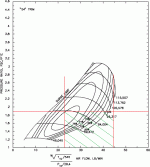
first is a map of a T-3 "60" trim sourced from www.turbocharged.com with the above variables blotted on it.

1.68 P/R, lower RPM flow at 19.65lb/min and upper limit at 39.9lb/min
T-3 60.gif

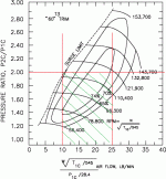
just for fun, I plotted the same over a T-4 "54" trim compressor map.
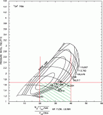
T-4 54.gif

the shaded green area is what the engine requires, assuming the VE% is correct along with the desired 3000RPM lower limit and 6000RPM upper limit.

once you find a map where the top right corner of the box, or where the lower CFM # and the P/R intersect, is not to the left of the surge line, the turbo is OK for the application and is not too big. Ideally you want to be in the center of the compressor map throughout the entire range, having the "islands" in there and the center one is the best efficiency output of the turbo.

now, by looking at the T-3, you can see that you are completely out of the efficiency range at that given Boost pressure and RPM.

lets take a higher PSI and plot them across the T-4 and T-3 charts.

for this pressure ratio we will go with 1.9, this equals 12.8PSI from the compressor.

For 6000RPM:
CFM = (7.0 x 6000 x 90 x 1.9) / 5660 = 1268CFM or 88.9lb/min. To convert this value to lb/min take CFM and divide by 14.27.

For 3000RPM:
CFM = (7.0 x 3000 x 90 x 1.9) / 5660 = 634CFM or 44.5 lb/min.

divide by 2, since there are 2 turbo's and upper limit is 44.45lb/min and lower 22.25lb/min
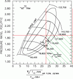
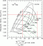
t-3 2.gif

T-4 2.gif


as you can see, on both T-3 maps, once you build boost you are completely off the map on being anywhere close to the efficiency range for the specified volume the turbo can put out.

the T-4 shows a better comparison on where it should be, but it still runs out of volume before peak RPM.

it is hard to find a turbo that the maps work well with a "low" boost numbers like above. I am sure there is one out there but it will take a bit of research....

BTW, i still claim to not be an expert. just slightly knowledgeable enough to get myself in trouble.
 
Last edited:
Thanks for working on this for me. Honestly it's a lot to digest at one gulp so I'm going to just nibble around the edges of it for a while. :thinkin:
 
Just out of curiosity, what really happens when a turbo is run outside of it's efficiency range?
 
Just out of curiosity, what really happens when a turbo is run outside of it's efficiency range?

The ratio, intake pressure to exhaust pressure, changes oddly and rapidly. In this situation, you are probably running in the 40-55% efficiency range, as these maps map out 65+%. in doing so the compressor is requiring more from the exhaust side for the given pressure / volume needed on the intake side.

On MOST turbos, I see the people over driving them on the big end, example, 12 valve Cummins diesel, with a stock Holset HX35 turbo, running 30psi you are probably in the 70-75% efficiency range. that is the sweet spot for that turbo, but to get more boost, say 40psi, this in turn increases the air volume since the pressure ratio increases, making the needed pattern to shift up and to the right on the map, and it gets out of the efficiency range and over spins the turbo (the numbers to the right of the map is the shaft speed in RPMs, as they normally operate at 75K-140K RPMs), leading to bearing or shaft failure and makes them go do far out of their efficiency range that the air temp goes through the room and you are making more heat than anything, so you may get 5-10psi more boost but see a 100+* increase in air temps and that in turn negates any gains you may get from the 5-10psi increase.
 
to show an accurate representation of what would be an ideal RPM range vs. volume and RPM for the 427 motor, we will assume the pressure ratio comes out to be (14.7 + 14.7) / 14.7 = 2.0, 14.7 PSI out of the turbo.

upper limit is 3205rpm
CFM = (7.0 x 3205 x 90 x 2.0) / 5660 = 713.5CFM or 50lb/min. To convert this value to lb/min take CFM and divide by 14.27.

For 1282RPM:
CFM = (7.0 x 1282 x 90 x 1.68) / 5660 = 285.4CFM or 20 lb/min.

using 25lb/min as the upper limit, and 10lb/min as the lower, for the turbo to be in peak efficiency for the highest amount of time, in relation to the volume of air your motor needs @ a 90% VE, you would have to have 14.7psi @ 1282RPM and have a max RPM of 3205RPM

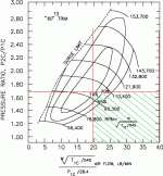
t-3 3.gif

that is ideally how a matched turbo should plot out in relation to flow and pressure for a given engine. you want as much of that center ellipse in the plotted area as you can get.
 
Last edited:
to show an accurate representation of what would be an ideal RPM range vs. volume and RPM for the 427 motor, we will assume the pressure ratio comes out to be (14.7 + 14.7) / 14.7 = 2.0, 14.7 PSI out of the turbo.

upper limit is 3205rpm
CFM = (7.0 x 3205 x 90 x 2.0) / 5660 = 713.5CFM or 50lb/min. To convert this value to lb/min take CFM and divide by 14.27.

For 1282RPM:
CFM = (7.0 x 1282 x 90 x 1.68) / 5660 = 285.4CFM or 20 lb/min.

using 25lb/min as the upper limit, and 10lb/min as the lower, for the turbo to be in peak efficiency for the highest amount of time, in relation to the volume of air your motor needs @ a 90% VE, you would have to have 14.7psi @ 1282RPM and have a max RPM of 3205RPM

View attachment 5736

that is ideally how a matched turbo should plot out in relation to flow and pressure for a given engine. you want as much of that center ellipse in the plotted area as you can get.

Well, I know I said I would prefer the turbos to kick in sooner rather than later, but somehow I am doubtful that I will EVER see that much boost at 1282 rpm. Nor would I want the turbos to peak out at 3200 rpm, neither.

So maybe I am just missing something here.....

I've been pondering what you are saying about the engine's VE (volumetric efficiency) and I'm a bit confused. I've been working a LOT with the VE tables in EFILive, and they are TABLES, not a single value. There is one table from 15 to 105 kPa (B0101) and another for boost (A0009) starting at 105 kpa and going up to 285 kPa. I think with the 14 lb springs in the new wastegates, I will be limited to under 200 kPa, IF boost will even reach that high. I've actually been massaging A0009 tonight, first from the data from my last logging run, and then filling in cells to make sure they won't be leaning out the AFR on me when I do run with the new wastegates.

But in any event, it would appear to me that there will be a whole range of VE values for an engine in relation to a turbo in real life, not just one static value. And then there is the thought I had that doesn't forced induction itself change the VE values? Supposedly you can reach a VE of MORE than 100 percent, but so far I haven't seen anything like that in my own VE tables. The most I am seeing in A0009 at 105 kPa and above from data actually logged is around 85 to 90 percent.

You know, I have to wonder how many people really check those efficiency tables (much less even know how to utilize them) when looking to pick out turbos for their cars? I've read a fair number of threads about people selecting or upgrading their turbos, and pretty much it goes "that one looks bigger, so it should be what I need".
 
Well, I know I said I would prefer the turbos to kick in sooner rather than later, but somehow I am doubtful that I will EVER see that much boost at 1282 rpm. Nor would I want the turbos to peak out at 3200 rpm, neither.

So maybe I am just missing something here.....

that was just a theoretical "at what RPM vs. Volume vs. Pressure would that turbo work in it's ideal efficiency range on your engine. that turbo is better suited for a smaller displacement engine than a 7L 427ci monster, err well 1/2 that a 3.5L 213ci engine. That turbo, the T-3 60 trim with a .63 A/R housing is optimal for a 2.3l motor. let me do a comparison on a 2.3L motor with 90%VE with 3000rpm lower limit and 6000RPM upper limit and 18psi as that is an ideal pressure easily obtainable and safe on a 2.3L turbo motor.

The pressure ratio comes out to be (14.7 + 18) / 14.7 = 2.22, 18 PSI out of the turbo.

upper limit is 6000rpm
CFM = (2.3 x 6000 x 90 x 2.22) / 5660 = 487.14CFM or 34.13lb/min. To convert this value to lb/min take CFM and divide by 14.27.

lower limit is 3000RPM:
CFM = (2.3 x 3000 x 90 x 2.22) / 5660 = 243.57CFM or 17 lb/min.

using 34lb/min as the upper limit, and 17lb/min as the lower, you can see this turbo would be well suited for use on a 2.3 engine. at a lower pressure ratio, maybe a 2.0 (14.7psi) it would likely be even more efficient than at 18psi.

Fig4.gif

now there are other variables that you can plot out IF you know your boost curve, like at what RPM you make 1PSI, what RPM you make 5PSI, and you can plot those marks up to your peak RPM and PSI readings to get a truer reading off of the map. this was just for generalization purposes, assuming you would be at PEAK boost at the lower RPM. I know 15-18 PSI can be made on a 2.3 with this turbo at 3000RPM. I have done it myself.

if you can provide me a map or list from 0PSI to 8PSI and the RPM ranges associated to the boost readings, I will plot them accordingly on the T-3 map for you to show the lb/min change across the board with RPM and boost varying.
 
I've been pondering what you are saying about the engine's VE (volumetric efficiency) and I'm a bit confused. I've been working a LOT with the VE tables in EFILive, and they are TABLES, not a single value. There is one table from 15 to 105 kPa (B0101) and another for boost (A0009) starting at 105 kpa and going up to 285 kPa. I think with the 14 lb springs in the new wastegates, I will be limited to under 200 kPa, IF boost will even reach that high. I've actually been massaging A0009 tonight, first from the data from my last logging run, and then filling in cells to make sure they won't be leaning out the AFR on me when I do run with the new wastegates.

But in any event, it would appear to me that there will be a whole range of VE values for an engine in relation to a turbo in real life, not just one static value. And then there is the thought I had that doesn't forced induction itself change the VE values? Supposedly you can reach a VE of MORE than 100 percent, but so far I haven't seen anything like that in my own VE tables. The most I am seeing in A0009 at 105 kPa and above from data actually logged is around 85 to 90 percent.

You know, I have to wonder how many people really check those efficiency tables (much less even know how to utilize them) when looking to pick out turbos for their cars? I've read a fair number of threads about people selecting or upgrading their turbos, and pretty much it goes "that one looks bigger, so it should be what I need".

yes, there are times when it will be over 100%, though rare on a street car. if you use the VE readings in your computer, it will give you a better look at the volume the engine would need at a certain PSI reading. they vary throughout the RPM band, but you will see at whatever the peak RPM is for your TQ output the VE value should be 98+%.

there are always variables that will cause the mapping to change, air density, barometric pressure, temperature, altitude etc. if you factor all those things into the equation then you'll likely never get a true answer to what is needed.
 
if you can provide me a map or list from 0PSI to 8PSI and the RPM ranges associated to the boost readings, I will plot them accordingly on the T-3 map for you to show the lb/min change across the board with RPM and boost varying.

Maybe I'm missing something, but it doesn't appear to be that simple to me to plot a single axis map relating engine speed (rpm) to boost (kPa). To give you a few illustrating examples of what I mean, I'm looking at the last log I captured and I see this:
  • 4703 rpm, 48% throttle, 69.0 kPa
  • 4706 rpm, 81% throttle, 88.0 kPa
  • 4895 rpm, 97% throttle, 150 kPa
  • 4920 rpm, 48% throttle, 71 kPa
  • 5501 rpm, 55% throttle, 112 kPa
  • 5531 rpm, 100% throttle, 144 kPa

All of the above are taken in the upslope of throttle engagement, and are not values taken during deceleration.

So engine speed is not the only determining factor of vacuum or boost in the intake manifold. And neither is throttle position by itself.

Heck, even using a 2 dimensional grid map that has engine speed on one axis and manifold vacuum/boost on the other will not show the same values at every intersectimg cell of those two axis while driving. While calibrating the VE tables, I have to take the AVERAGE of all the values produced for each cell, so obviously there is at least a third variable in a three dimensional grid necessary to properly plot what produces a set (and predictable) value of vacuum or boost.
 
Ideally, and this could be done on a dyno or "on a closed course with a professional driver", you would need to be in 4th gear, assuming it is the 1:1 ratio in the trans, and do a 1500-2000RPM start up to your max RPM, but this would need to be at WOT, 100% throttle as that is the constant needed for the above chart to work for me. with this info, you will know when boost starts, when it peaks and holds at max PSI. using this info I can plot the graph from an off-idle scenario and this will help understand the volume needed in relation to RPM and boost as the boost pressure will manipulate the volume numbers on the X axis.
 
Last edited:
Maybe I'm missing something, but it doesn't appear to be that simple to me to plot a single axis map relating engine speed (rpm) to boost (kPa).

I will use the engine speed and boost for that specific engine speed to plot the flow, in lb/min or CFM, across the map at that specific pressure ratio. so the boost number will help equate the number on the Y axis, and the pressure ratio along with the rpm, VE% are used to calculate the flow, or volume needed/used and plot it on the X axis
 
Ideally, and this could be done on a dyno or "on a closed course with a professional driver", you would need to be in 4th gear, assuming it is the 1:1 ratio in the trans, and do a 1500-2000RPM start up to your max RPM, but this would need to be at WOT, 100% throttle as that is the constant needed for the above chart to work for me. with this info, you will know when boost starts, when it peaks and holds at max PSI. using this info I can plot the graph from an off-idle scenario and this will help understand the volume needed in relation to RPM and boost as the boost pressure will manipulate the volume numbers on the X axis.

Ah, well, neither one of those appear to be likely anytime soon, if at all. I only know of two places close by (South Georgia Corvette and SS Performance) with dynos, and neither one of them are going to ever have my cars in their shops.

As for a "professional driver" and a closed course, not sure where I could find something like that nearby. I believe redline on the engine is 7000 rpm if I remember correctly, so not likely I could (nor would want to) do that on even the little traveled roads around here.

I appreciate all the insight you are giving me with this, but I'm not sure there is going to be any feasible way to give you the data needed to try to identify the best turbos for my setup. Actually, the way my luck runs, there probably doesn't exist such a beast anyway. Looking at my data logs, I can see incoming air temperature rising pretty rapidly while I am in boost, so I guess STAYING in boost for long periods of time wouldn't be a good idea for me to do. Not that I have been intending to do so anyway....... :hehehe:

So maybe by the time I wear out the turbos I've got and start looking around for replacements I'll have a better understanding of exactly what I need to be looking for. But for now, unless I find that there is a severe problem using what I've got, I guess I've got to be satisfied with them and what they can do.
 
Back
Top