• Got the Contributing Memberships stuff finally worked out and made up a thread as a sort of "How-To" to help people figure out how to participate. So if you need help figuring it out, here's the thread you need to take a look at -> http://www.corvetteflorida.com/forums/showthread.php?t=3581 Thank you, everyone! Rich Z.

427 engine (part 2) - RHS block

Don't hack the firewall, move the engine forward.....:lmao::lmao::lmao:
Good luck finding a solution Rich. :yesnod:
Andy :wavey:
 
I think I am confusing you with my idea so I hope this will make it a little clearer as to what I see as a fix for the fuel rail plug problem.
BAnjo.jpg
 
I think I am confusing you with my idea so I hope this will make it a little clearer as to what I see as a fix for the fuel rail plug problem.
View attachment 5486

Yes, that would work fine, I think. The problem is FINDING it.

Does anyone happen to know offhand what the threading is on the end of those FAST fuel rails?
 
Another thought has just occured to me. When you find out what the thread size is on the rail you might think about the 90 degree banjo. That way you would be able to run the return line back along the fuel rail for a neater installation.

I believe if it says 8an washer then the thread is probably the same as an 8an hose fitting.

Went to the Fast rails site and now I see what they are doing. The part I thought was a reducer is actually an adaptor so you can connect the female fitting from the hose to the fuel rail.

If you have an 8an male end laying around you could see if it will go into the fuel rail in place of all those adapters. If so you will know the size of the fuel rail thread. Then all you need is the banjo bolt for that size and the banjo for the bolt. I hope this helps solve this problem.
 
Last edited:
I've seen two designations of the threads in the fuel rail (1) -8 SAE and (2) -8 AN O-RING.

But yeah, I think getting a male fitting that would screw directly INTO the end of the rail would be better than a female fitting that fits onto the F.A.S.T. fitting and perhaps give me the clearance I need.

And I think it's a 180 fitting you are referring to as that would be a "C" shape and probably need less clearance than a 90 degree, which would be perpendicular to the rail. I'm going to see if they make a 120 and 150 degree fitting as well. If I do have to cut the firewall, I need to keep the damage to the bare minimum.
 
Whoa, hadn't checked-in in a while. Glad to see Kenny was able to drop by and help you out. Now, you just need him to stop by more often. LOL
 
In reference to the earlier posts about the vacuum line to the fuel pressure regulator, the guy who is going to be doing my tuning recommends that I DO have the vacuum line hooked up.

I've been doing some reading about this, and apparently there are two ways to control the issue of variable fuel amounts needed from idle to WOT. The problem is that there is MORE vacuum available at the fuel injectors at idle than at WOT, even to the point where at IDLE, the injectors themselves are actually subject to a suction effect that will draw out more fuel than injectors simply being opened at zero vacuum. I'm still trying to wrap my brain around some of this so bear with me.

Anyway, there are two methods used to adjust the actual amount of fuel that the PCM calculates for the injectors to provide that will be variable depending on the vacuum inside the manifold and referenced via the MAP sensor. One method is via the vacuum line going to the fuel pressure regulator which will then mechanically control the amount of fuel pressure it provides to the fuel rails. In this case, the regulator provides less fuel pressure at high vacuum levels and increasingly more pressure as vacuum is reduced and even going into positive pressure (boost for forced induction). The other method, and the one that is used in the stock C5 Corvettes (probably other generations, too), is to do this programmatically via something called the Injector Flow Rate Table. Which looks something like this...

ifr_table _SGC01.jpg


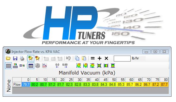
What this table does is programmatically act like what the vacuum line does that would go to the fuel pressure regulator. That is, it adjusts the amount of fuel referenced to the vacuum in the intake manifold that the PCM commands the fuel injectors to deliver to the cylinders. As you can see in the table above, the values are variable depending upon vacuum in the intake manifold. If the vacuum line were hooked up to the fuel pressure regulator, than those values would all be the same, which would be the actual flow rate of the injectors.

Now there is a lot of negative logic going on, that I am still trying to come to grips with, but basically kPa is actually PRESSURE, so 0 kPa means zero pressure, which means MAX vacuum (idle), and the value at 80 kPa means max pressure (up to sea level barometric pressure), which means zero vacuum (WOT - or pretty much ambient barometric pressure). Basically the amount of air coming into the engine has stabilized to where all the air needed is being provided.

Also note that the higher the values in the cells in the table, the LOWER amount of fuel being commanded to the fuel injectors. In effect, the table TELLS the PCM the flow rate of the injectors for a given amount of vacuum. The fuel injectors I have in that engine are rated at 72 lb, so it appears that this table is fooling the PCM in my car into thinking that the injectors are LARGER than they actually are, so that it will command a smaller duration opening of the injectors as the PCM tries to calculate how much fuel that the injector needs to deliver to the cylinder, and therefore run leaner than if the 72 lb values were being used. Since the PCM thinks the injectors are larger, it needs to hold the duration of the injector being opened a LESSER amount of time. So, in effect, the smaller the number in that table the longer the duration, and therefore MORE fuel, being commanded to the fuel injectors. Like I said, NEGATIVE logic here...

Now, looking at that IFR table above, it's really confusing, at least to me. 100 kpa is actually 14.5 psi, which is pretty close to sea level air pressure (14.7 psi). So the assumption must be that the furtherest right hand cell must be WOT, and the left most cell must be idle, IF we are really talking about kPa values for that table. But if this is true, the VALUES in those cells are the REVERSE of what they should be. At idle, the value in that cell is 79.7, and at WOT, that cell is 87.7. So what this means is that the PCM is being hoodwinked into believing that thru all levels of manifold vacuum, the injectors are LARGER than the 72 lbs injectors I actually have. And more to the point of my confusion, the injector values at idle will deliver MORE fuel than the injector values indicated at WOT. Remember, smaller values will deliver MORE fuel than the larger values in that table.

The only way this table does make sense to me is if those cell labels are NOT actually kPa, but instead a relative VACUUM level, meaning that the table actually is indicating WOT at the left most cell, and IDLE at the rightmost cell. Then the values in those cells DO make sense, with less fuel being provided at idle and MORE fuel being provided at WOT.

I know the above is probably a jumbled mess, but I'm just trying to figure this all out, and maybe trying to EXPLAIN it will help me UNDERSTAND it a little better.... So if anyone else can figure this out and explain it to me, PLEASE do.
 
Got the driver's side half shaft out today. That one was MUCH easier to get out. Probably because I've been spraying it with PB Blaster for a while now. And that GM tool for the job probably helped some.

Also got the hub separated from the knuckle and will be cleaning up all the stuff before I put the new shaft back in and put everything back together again. The second time doing this almost feels like old hat to me. Probably because I kinda feel like I know what I'm doing this time. On the other side, most of the time I was thinking, "Oh Lordy, what am I getting myself into now?"
 
Got the rotor center de-rusted and painted (next time I'm going to get a two piece rotor with an aluminum center piece), also cleaned up the caliper bracket and painted that red. Got the knuckle all cleaned up an shiny. Ran the bolts through a die to clean out the red Permatex crud left on the threads. Just got to let the paint cure, and clean up the upper and lower control arms, and I'll be ready to put this driver side shaft back in and be done with this.

Then on with the fuel system....

Still haven't found anything that will work like I want it to on that driver side fuel rail for the clearance issue. So if I want to plumb it like it SHOULD be plumbed, I may have to just bite the bullet and cut into the firewall. I did find 120 and 150 degree AN-08 fittings, so I have them on order to see if they will help keep the cutting down to the bare minimum.

I even went so far as to locate some shorter motor mounts (http://hinsonsupercars.com/p-1351-hms-urethane-engine-mounts-shorter-version-c5c6gtorx7.aspx) thinking that perhaps lowering the engine a bit (the firewall slopes back and down somewhat), but replacing the motor mounts looks like more trouble than just cutting the firewall. Those STS pipes up front will be in the way trying to lower the cradle to get the motor mounts changed out. Plus I think I would have to remove the passenger side header. The intake manifold is pressed right up against the firewall cowl, so lifting the engine any is out. That's ALL I would need is to crack the intake manifold....
 
Yee Hah thats what I was hoping for. You must have gotten somebody to measure it and take a picture. Sure do wish they would publish a chart with the dimensional stack up of all the banjo fittings and bolts.
 
Yeah, I'm trying to verify with FAST that the threads on this thing are compatible with the threads in the fuel rails before I go and order it. I'll likely just go ahead and get the -08 fittings I need for the front of the fuel rails to replace the -06 fittings now in there from them as well, IF the threading is correct.

The good thing about this banjo fitting is that I can swing the angle up or down as needed to clear the firewall with the fitting that screws onto it. I've got a whole slew of different angled -08 hose fittings on order (I originally bought a bunch of -06 fittings to clear the intake manifold, that I was able to send back for exchange), so I'm sure one of them will work out perfectly for me. Well, I HOPE so, anyway....
 
With any luck, I have found what I need for the back of that driver side fuel rail.

That comes out to 1.1 inches so yeah, that's right in the ball park I need.

http://shop.nukeperformance.com/an-hose-ends/an-fittings/34-unf-an8-banjo

Had to go to a website in Sweden to find this, though.

Well, I do have to say that I have met some very nice people through this disaster. The guy who runs that site mentioned above has offered to send me the stuff for free to help me out. That pretty much shocked me, as it is doubtful he would ever get a ton of business out of me being over in Sweden. I was looking to buy -08 fittings for the front of the fuel rails as well to replace those -06 fittings that are not on there, but expressed some misgivings about the threading being correct. He just said to give him my shipping address and don't worry about it. :thumbsup:

Then one of the guys over on CorvetteForum who has the business at http://www.ccperformanceparts.com/ sent me a box of heat wrap for my exhaust system along with some wrap that goes across the tunnel plate. Didn't ask for a dime in payment for the stuff. :thumbsup:

And there were some others along the way that I've mentioned in the past as well.

In a way it almost makes up for being crapped on (in my opinion) during my past experiences with the shops that worked on my car. :thumbsdown:
 
Well, after talking to an advisor with Chase at length today, they are going to place a chargeback on South Georgia Corvette's account for $4,000. Apparently Aaron Scott already recently refunded $2,000 to my account prior to this chargeback taking place. The advisor said he expected Mr. Scott to contest the chargeback, which he will deal with as needed.

On Tuesday I sent Chase a message again explaining the circumstances and I attached a bunch of photographs to support my claim. Apparently that helped them to come to this decision, using those photographs as evidence to support my claim. Fortunately I have taken photographs and video of every problem I have found on the car that I can attribute to Aaron Scott in one way or another. Which, of course, nearly all of this has been documented here and on CorvetteForum. I learned my lesson about DOCUMENTATION when things like this happen.

As for my car, I'm waiting for brake parts to come in. The new pads and rotors should be here tomorrow, so I will be able to put the rear end suspension back together and start working on the front.

I bought some gas cans so I can drain the gas tanks and extract that fuel pump. Nate at NastyPerformance mentioned to me that I can jumper the in tank fuel pump at the fuse box to use that to quickly drain the tanks. But I think that 2 second timeout without the engine running would be an issue. Anyone know how to get around that? I don't think the Aeromotive can suck out the gasoline if the in tank pump isn't working, can it?

While I was poking around underneath the car today, I found two nuts holding the transmission brace in place were not tightened down. I hope the ones on top are tight as they will be a bear to get to if not.

The advisor at Chase (who seemed to be a car guy himself) asked me how long before I would hope to get my car on the road. I told him I'm guesstimating by the end of March. Then the guy started asking me questions about buying a Corvette himself. :thumbsup:
 
Surprisingly those fuel rail fittings from Sweden (NukePerformance) showed up today via DHL. I was surprised at how quickly they got here.

nuke_01.jpg


Looks like pretty good quality stuff, but I'll know more when I go to actually install them. HOPEFULLY the threading is correct for the inside of the fuel raise. This could very well solve my clearance problem. :thumbsup:

On another front, the brake stuff showed up, and all in all the stuff looks like decent quality, especially for the price.

rotor_01.jpg


rotor_02.jpg


rotor_03.jpg


rotor_04.jpg


Brake pads looked OK to me, but I'm not an expert in them, and I guess the proof of the pudding will be when I drive with them.

pads_01.jpg


pads_02.jpg


pads_03.jpg


But one fly in the ointment was that I noticed that one of the four rotors was not inside a protective plastic bag like the others, so I looked at it more closely. Darn, looks like at the edge of the hat on one of the rear rotors, it got scraped or dinged or something and that took off the zinc coating exposing the bare metal. I looked more closely at the box, and it appears to me that it has been retaped shut. So my guess is, based on the evidence, that someone swapped out those rotors in that box I got, and I got the short end of the straw. I've contacted the seller to see what he will do about this. I know they were cheaply priced, but still.......

rotor_05.jpg
 
Last edited:
I feel like I am FOREVER waiting on something lately. Haven't gotten a tracking number yet on the replacement rear brake rotors. Then I sent back a bunch of -06 AN fittings to ANplumbing.com to exchange for -08 fittings, which arrived there on 02/18 and they are acting like they didn't get the box. Luckily I got delivery confirmation with USPS when Connie shipped it out for me.

So I ordered some stuff from Summitracing today, and when that comes in I'm going to start draining the gas tanks. A guy on CorvetteForum gave me a real handy tip on how to run the stock fuel pumps even when the engine isn't running...
Rich,
You can use your HPTuners Scanner program to turn the fuel pump ON without the engine running. Connect the cable, turn your key to the ACC position, and start the scanner. Open up the VCM Controls window, hit the Fue & Spark page, and toggle the Fuel Pump ON.

VCM Scanner > VCM Controls > Fuel & Spark > Fuel Pump > ON

That should come in REAL handy... :thumbsup:
 
Back
Top